Bolts in FEA [5]: Complex Bolt Model
This is the 5th installment of the “bolt series”. In this article we will discuss: An Advanced Model…
30 September 2024Bolted connections must be one of the most dreadful things to model in structural FEA. I guess this is why they are so often ignored!
Modeling bolted connections leads to many Finite Elements (and a lot of work), or relatively low accuracy if sub-par solutions are used. Let’s navigate through all the possibilities!
This time, I will try something new. I divided this article into parts to make each one shorter and easier to digest. I hope that you will like it this way!

If you have a bolted connection in your model, there are several approaches you can have. I will address those in the series of articles, discussing the most important things along the way. This is what you can read about:

I would say, there are two situations when bolted connections can be ignored.
The first one will be rather obvious, as I guess it wouldn’t cross your mind to model connections when you are making a beam model, but with 2D mesh models, things are a bit more problematic…
… let’s start at the beginning!

This is a perfect scenario, to be honest. You can ignore modeling bolted connections, not because it’s nearly impossible to model those in the beam model anyway. The reason is much deeper:
Beam models provide you with internal forces in each member (and as a result, in each connection).
This makes it easy to design the connection by the code, outside your FEA model.
Simply put, your FEA model will show you internal forces in beams (be it tension/compression, bending, or shear) in the area of the connection. And your connection has to transfer those forces.
Designing such a connection is rather simple per the code of your choice (i.e. EN 1993-1-8). It also only takes minutes to do, so much less than any FEA modeling! You can even make an Excel/Mathcad tool to calculate such things for you.
There is just one thing to remember: Connection Rigidity!
Sadly, this is not where the story ends. While you may not have to model the connection, it still impacts your model’s behavior.
Some connections will allow for rotation easily (those are usually called pinned connections), and some will be rigid and will transfer all the bending. Some will transfer bending only in a selected plane while allowing for rotation in the other.
So while you’re not modeling the connection, you still should look into the releases at the end of your member where the connection would be, and decide which internal forces can be transferred by the connection there. Luckily, this is just a few clicks in a typical beam FEA software.
MORE READING FOR LATER:
If you are interested in learning more about connection rigidity, you can read my older posts:
Now, let’s get into the more complicated things!

As soon as we start considering models using 2D plate/shell elements, things become more complicated. Sadly, we don’t get nice info about the “total internal forces” that the connection has to transfer.
Oftentimes the connections are long, have weird geometry, or unevenly spaced bolts… and suddenly, the “design by the code” approach becomes problematic.
Funny enough, you can ignore the bolts if you can reliably design that bolted connection by the code.
In essence, you should be able to accurately establish forces, that each bolt should transfer. Those forces can be read from your FEA model, of course. The challenge is, to establish those forces, from the model that doesn’t have a connection in it.
This can reliably be done in several cases:
Uniformly loaded lap-joints
Assuming that I would not be worried about the eccentricity, I feel comfortable when modeling such a connection as a “continuous plate”, as long as several conditions are met:


Assuming that the above is true, then modeling the lap joint as a continuous plate (without any details) is reasonable. In such case, simply checking the force in the joint, and then designing it by the code is a practical approach, that will save you an insane amount of time!
Especially since you can make an Excel Spreadsheet (or Mathcad file, or whatever you use) to calculate this automatically for you.
And if you feel intimidated by the amount of manual calculations, and digging through the codes, don’t worry! I’ve got you covered. You can get my 1-page guide on how to perform such calculations below:

Uniformly loaded end-plate connections in tension/compression

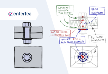
This one is far more difficult than it may seem. Truth be told, you rarely get uniform tension/compression in end plate connections in 2D mesh models, like the one I draw above.
But, let’s assume that you have such a rare case. If so, this is great!
You can simply model the end plates in your FEA model (I simply sum the thicknesses of the end plates in most cases). Then read the tension/compression membrane stress in the vertical plates in your FEA model, and just as in the case of lap joints, calculate the force per length your connection has to transfer.
The rest is a simple design by the code, and you’re done!
Just don’t forget about the prying action and bending of the end plate, which must be verified manually (as this simplification does not include this in your FEA model).
The above is the ideal case, so let’s wonder why I wrote that this rarely happens. The main culprit is out-of-plane bending!
End Plate connections and out-of-plane bending

In most plate/shell models you have some sort of pressure acting as a load (be it pressure, liquid, bulk solid, whatever). This is how most loads are “generated”.
And while such pressures will really cause uniform tension/compression in walls, this is not the only internal actions they will generate. Sadly, in most cases, the out-of-plane bending appears – just as I marked above.
This is problematic… our simplification from the previous case won’t hold here!
Sure, we can assume that the end plates are “just a stiffener”, and ignore the bolts. But this would make our model too strong! There are several competing effects here, and we need to consider all of them together:
So, as you can see, such a connection under uniform tension/compression is easy to ignore in FEA. You will have a simple time designing it by hand later on.
However, in most practical cases, when the out-of-plane bending appears, the stress state is too complex for hand calculations. I mean, it would be doable to still calculate this by hand… it will be just faster to simply model the connection, though.
Fair warning:
This out-of-plate bending thing can really catch you off guard, and I’ve seen my share of wrongly calculated models that would lead to serious issues because such connections were ignored.
I genuinely understand that modeling this is a LOT of work – but it appears that properly designing this without modeling the connection is even more work!
Whichever route you will choose, just remember about all the effects I’ve listed above to avoid problems with your designs!

Join my 2h FREE Live Event and learn all that you need to know to start using Nonlinear FEA as an Expert! I will talk about:
I feel that every article about “ignoring something” or “simplifying something” should contain such a cautionary chapter.
I mean, it’s great to simplify stuff – I love to do this. But too much of a good thing, will lead to serious troubles! Instead of boring you with cautionary tales, I will simply show you the impact of oversimplification on an actual design case.
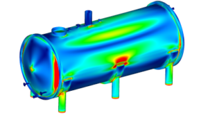
This is a typical hopper design:

You will notice for sure, that we have the connection modelled (if you look at the closeup, you may even notice the bolts and opening).
However, for the purpose of the demonstration we simply applied “glue contact” to both ends of the connection – this is almost the same thing, as modeling “double thickness” of the end plates in a single stiffener.
As you can see, the stress distribution is nice and uniform, and plastic strains are easily acceptable.
However, as soon as we actually consider the connection (normal contact + bolts) things start to go seriously wrong:

Suddenly, the design is insufficient, and strengthening is really required!
Not considering such connections in design is a serious error, I’ve seen far too many times already!
This also nicely highlights the complexity of such connections, as there are many effects from the list I gave you happening here.
Good advice:
Always think if the simplification of the connection will lead to a safe design.
Undoubtedly, it will lead to faster design… but will you be able to thoroughly check all the effects in the connection in by the code calculations later on?
Remember about:
- Bending of the end plate due to pry-action
- Out-of-plane bending of the end plate
- Bolt bearing stress
- Weakening of the stiffener due to bolt openings
At the very end of this part of the bolt series, I want to describe an approach you may want to try out. I did that on several occasions, and I never regretted it.

In this article, I’ve told you, that when you have a lap joint, that is nicely uniformly loaded with no bending or other funny stuff, you can ignore it.
However, along with the connection, you are also ignoring the eccentricity it causes.
In most cases, this is not an issue, but what if you are calculating a big tank (or something similar), like the one below:

In such a case, there is a thought worth considering:
If my tank will be empty and wind action or underpressure (or both) will be present – will this eccentricity lower the buckling capacity of the tank shell?
Undoubtedly, this will have some impact. Usually, it will be rather small, but for big tanks, with a lot of those joints… it’s worth checking I would say!
Of course, this doesn’t mean that you have to model all the joints. I mean, for such a big tank, it’s just impossible. But… you can model all the eccentricities!
All you have to do, is to model the tank in “layers” – just as it will be built. So there will be a checkered midside layer (below in green), and the filling plates will overlap the plates from the midside layer from inside and outside, as the detail shows.
This way, all you need to do, is to model the glue contact in areas where the plates overlap, and you’re done!

Sure, you will still have to calculate all the joints by hand, by reading forces from the model as we already discussed. But the benefit is, that now, you have all the plate eccentricities included in your model, so your stability calculations will consider those as well:

I’m mentioning this here, simply to point out, that with reasonable modeling, you can pick and choose which effects of the connection you want to have in your model.
You can simply decide which things to include, and which to ignore in FEA. Of course, you will have to verify the ignored components with the design by the code at the later stage, but you should not be afraid of this – it can save you a LOT of time on many occasions.
Super accurate models are great, but oftentimes, simplifying them and calculating selected details by the code is simply a better approach!
Of course, on many occasions, the situation is complex enough, that you simply have to model the bolts…
This is something I will address in the Part 2 / Part 3 articles of this series, so stay tuned!



Share
Join the discussion