This is a 3rd part of the post series addressing reasonable approach to bolt modeling.
Learn what you should consider when modeling bolts. Should you aim to have an uniform stress distribution. Or maybe not to strengthen the plates unnecessarily with your bolt modeling? It’s all discussed here!
This is a continuation of the previous posts. You may want to start with the previous posts if you haven’t read those already:
PART 1: Ignoring Bolts.This part focuses on when you may ignore bolts in your FEA models and how to do it. There is even a great PDF guide you can download to help you with this (get it below this list)
PART 2: Failure Modes of Bolted Connections. This article discuss how the bolted join may fail in many surprising ways. This is important, as it will guide our decisions on what to pay attention to in bolt modeling.
Simplify Your FEA Models, Maintain Design Accuracy!
What to pay attention to when modeling bolts?
From the previous post you know already what failure modes can happen in your connections.
Now, let’s wonder which things you should pay attention to when modeling the connection. This is important, as it will influence your modeling choices.
Knowing what to can pay attention to, will show you which failure models you can capture in your FEA. This in turn will tell you which models are not covered. Those you will have to check later by the code.
Bolts modeled in FEA
This is the first thing. It may seem weird, but bear with me. As we discussed in Part 1, there are instances where you can ignore modeling bolts. Of course, in those cases you don’t need to have bolts in your model! Including bolts in your model is clearly an important first decision you will make!
It goes without saying that you should correctly represent the location of bolts in the connection. Also the contact between connected plates should be there when it will play a role (it will in most cases!).
How to Reasonably do Nonlinear FEA
Join me for free on October 20th
Join my 2h FREE Live Event and learn all that you need to know to start using Nonlinear FEA as an Expert! I will talk about:
Correct stress distribution around bolt in tension
Stress distribution near the bolt will depend on the simplifications in your modeling. In some failure modes, you should aim at a “reasonable” stress distribution from tension around the bolt.
Your model should take the force from the bolt, and put it into the plate in a reasonably accurate manner. Note, that this DOESN’T necessarily mean that the stress should be “uniform” around the circumference!
Point A: In the above connection stresses “behind” the bolt are lower. This is an area further away from the perpendicular plate in the middle. This means that this area is less “rigid” (as the plate has more length to deform). As a result, bolt will apply less load on that side.
Point B: On the “inside” between the bolt and perpendicular plate, the plate is more rigid (it deforms less). This means that bolt will apply more load on that side. This shows, that a “reasonable” force distribution around of the circumference is not the same as “uniform stress distribution”. This may impact some of the capacity checks, if you wish to perform them directly in FEA.
Point C: Another consideration would be the diameter of the opening/bolt you wish to model. It seems that the opening diameter is a natural and “easy” choice (since it’s already in the model). But in some cases (i.e. punching shear through a thin plate) making a model that allows to distribute the load under the entire washer may be reasonable. Of course assuming you wish to calculate punching shear in FEA.
One last Note: When it comes to diameter (mentioned in point C) you can theoretically select diameter to be “zero”. All you need is to connect 1 node from each plate with a beam. However, this does not meet the criteria discussed here.
However, your model may be ok with such an approach. You will simply have to check some failure modes by the code later. This means, that you don’t have to include them in your model.
Correct stress distribution around bolt in shear
This one is much easier to imagine, but much more difficult to actually consider in FEA.
If your bolt is in shear it will transfer that shear as contact to a portion of the opening circumference. The bolt simply touches the part of the opening circumference. Of course, stress in the plate (resulting from this shear) will NOT be uniformly distributed around the circumference!
Point A: I’ve marked the bolt position, and on this “side” of the opening shear is transferred as a contact. So it’s there, as there is contact between bolt and plate.
Point B: On the opposite side, the bolt is not touching the plate at all. So obviously, there will be no shear load transfer there!
This is important as most common solutions for bolt modeling lead to an uniform stress distribution. This makes it basically impossible to perform some capacity checks in FEA (unless you use more advanced modeling techniques).
Proper Weakening of the plate
Some failure modes are associated with plate failure in areas where it’s weakened by the openings. In those cross-sections there is less material (due to openings) and the connection is more likely to fail there.
However, for such failure modes to work, your FEA model needs to properly mimic this behavior.
This means that filling the opening with a Rigid Elementwill not work. Since Rigid Elements are infinitely strong (and connect all nodes at the circumference of the opening) this is an issue! Such “filled” openings actually strengthen the plate (due to indestructible RBE2) rather than weaken it!
This means, that if you want to catch such failure modes, you can’t input your bolts this way!
Proper Distribution of Forces inside the bolt
This has two layers. The more obvious one is, the tensile load and a shear force. Usually you will get decent values when you model bolts for those two.
Practical Tip:
There is only one thing I worry about when modeling bolts for tensile and shear force.
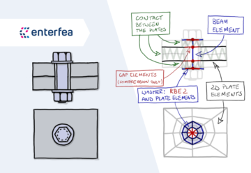
Usually, you model RBE2 elements in the openings, and the plates have contact between them on entire area. But this means, that the nodes that the RBE2 is attached to, can also “contact” one another.
This on some occasions can lead to a situation where you can have a very short (but infinitely rigid) lever, that would artificially increase load in the bolts.
Removing the contact from those nodes usually solves the problem!
Of course tension and shear are not the only things you may need. And this is the more complex layer of the problem.
If you would like to analyze bending of the bolt, it’s doable. But to do that, you would like to have a decent bending moment distribution along the bolt. This is way more difficult than it may seem.
Simply put, if you have 2 plates modeled as 2D mesh in midsurfaces (as shown above), this means that they are “one thickness” apart in your FEA model. This means that the bolt that transfers shear will also be bent because of eccentricity. In reality there is no bending (or at least not that much).
Sure, you can say, that the shear in reality is not “perfectly” only in the shear plane. That the stress on the bolt is applied on the certain “height” (usually with triangular distribution). And that causes some bending in the bolt. Still, this is widely ignored in bolt calculations (at least in EN 1993-1-8). But if you model the midsurfaces, you actually get that bending moment in your bolt. And this may complicate things for you.
So, if for any reason you want to properly catch bending of the bolt, you would need a solid model (or some crazy shenanigans). Just be aware of this!
Increasing Model Complexity
As you can see, there are plenty of things to worry about, when you model your bolts. And while some are obvious and easy to achieve, some will be way more challenging.
But the biggest issue is, creating the model, that combines various considerations together. You know, something that will distribute tension stress, and shear stress correctly around the circumference at the same time!
If you have bolts that only transfer shear or only transfer tension you are in a pretty decent place. Especially if you are willing to check some of the failure modes later by the code.
In such cases, things are actually not that bad! In the next article we will discuss a bolt model that I use the most. We will also check how it can help you (and with what).
This is not the only option of course! You may want (or need) to analyze things together. Especially if you can’t isolate some failure modes, because other stresses in your model would impact them. In such cases, modeling will require way more effort. We will discuss that in one of the future articles as well!
Be aware, that every additional failure mode you check in FEA increases the complexity of your model.
This is a game of diminishing returns. You may get to a place (especially with a lot of bolts in the model) that it simply is more efficient to check some of the failure modes by hand! Even if you have to use pen and paper to do so!
Please Remember:
You can totally analyze every failure mode of bolted connection in FEA.
But the fact that you can, doesn’t mean that you should! It will often be true, that it’s more efficient to check at least some of the failure modes by the code.
Still, it’s good to know how to do it in FEA, because from time to time, you will end up with a connection where you can’t simply “isolate” failure modes to check them one by one. This is true when other stresses in your model interact with your bolted connection.
But this is a consideration for another article! Just be aware that this can be the case (and sadly, is the case more often that you would like, as you will learn later).
Thank you for reading! I hope that you enjoyed this!
I have over 10 years of practical FEA experience (I'm running my own Engineering Consultancy), and I've been an academic teacher for a decade. Here, I gladly share my engineering knowledge through courses, and on the blog!
Each Tuesday you will get awesome FEA Content directly to your email!
How to Reasonably do Nonlinear FEA
Join me on October 20th!
On this FREE Webinar You will learn:
How Nonlinear FEA really works
What to pay attention to during Analysis Setup
How to Analyze and Understand Outcomes
… and much more!
We use cookies on our website to give you the most relevant experience by remembering your preferences and repeat visits. By clicking “Accept All”, you consent to the use of ALL the cookies. However, you may visit "Cookie Settings" to provide a controlled consent.
This website uses cookies to improve your experience while you navigate through the website. Out of these, the cookies that are categorized as necessary are stored on your browser as they are essential for the working of basic functionalities of the website. We also use third-party cookies that help us analyze and understand how you use this website. These cookies will be stored in your browser only with your consent. You also have the option to opt-out of these cookies. But opting out of some of these cookies may affect your browsing experience.
Necessary cookies are absolutely essential for the website to function properly. These cookies ensure basic functionalities and security features of the website, anonymously.
Cookie
Duration
Description
cookielawinfo-checkbox-analytics
11 months
This cookie is set by GDPR Cookie Consent plugin. The cookie is used to store the user consent for the cookies in the category "Analytics".
cookielawinfo-checkbox-functional
11 months
The cookie is set by GDPR cookie consent to record the user consent for the cookies in the category "Functional".
cookielawinfo-checkbox-necessary
11 months
This cookie is set by GDPR Cookie Consent plugin. The cookies is used to store the user consent for the cookies in the category "Necessary".
cookielawinfo-checkbox-others
11 months
This cookie is set by GDPR Cookie Consent plugin. The cookie is used to store the user consent for the cookies in the category "Other.
cookielawinfo-checkbox-performance
11 months
This cookie is set by GDPR Cookie Consent plugin. The cookie is used to store the user consent for the cookies in the category "Performance".
viewed_cookie_policy
11 months
The cookie is set by the GDPR Cookie Consent plugin and is used to store whether or not user has consented to the use of cookies. It does not store any personal data.
Functional cookies help to perform certain functionalities like sharing the content of the website on social media platforms, collect feedbacks, and other third-party features.
Performance cookies are used to understand and analyze the key performance indexes of the website which helps in delivering a better user experience for the visitors.
Analytical cookies are used to understand how visitors interact with the website. These cookies help provide information on metrics the number of visitors, bounce rate, traffic source, etc.
Advertisement cookies are used to provide visitors with relevant ads and marketing campaigns. These cookies track visitors across websites and collect information to provide customized ads.





Share
Join the discussion