
Bolts in FEA [5]: Complex Bolt Model
This is the 5th installment of the “bolt series”. In this article we will discuss: An Advanced Model…
30 September 2024We already covered what can fail in a bolted connection, and what you should pay attention to while modeling bolts. It’s time to get practical!
Today, I will show you a simple bolt model I use in most of my FEA models. It allows me to represent the most important aspects of the connection in most cases, although it also has limitations that I will address as well.
This is the 4th post about bolts in FEA. If you missed the previous ones, I would highly advise starting there:

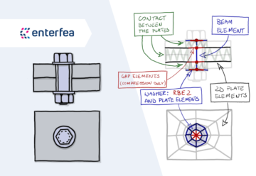
Firstly, let’s take a look at the model itself, and then we will wonder which things it does well, and where it fails.

As you can see, the model is pretty simple. It consists of 4 components:
Of course there are various considerations associated with such bolt modeling. For example, how many elements around the opening circumference is a good amount, and how the mesh should look like.
As you can imagine, meshing is very model dependent, but I like to keep at least 8 elements around the circumference. And I often “lock” the bolt region with a square/rectangle to allow the rest of the model to have a nice mesh. Above I’ve sketched how you can make a nice transition from “circle” to a square.
This meshing approach also has a neat benefit. You can increase the mesh density around the opening by increasing the amount of elements along the “spokes” (along the opening radius). You simply make more elements in that direction if needed, and you don’t have to remesh the rest of the model!

If you want to use this approach, immediately you will come across a problem. It’s not obvious at all, which diameter to use, for the rigid element representing the bolt/plate interface.
It seems that there are a few possible choices:
As you can imagine, this is a super complex issue, and every answer is in some sense “wrong”. Mostly, because this is a simplified model of course.
That being said, from the practical standpoint, there is only one thing you should think about when making the choice. But we will look at both sides of it:
Openings Introduce “Additional Rigidity”
As you know, we are using infinitely rigid elements. It goes without saying that they are way more rigid than the rest of your model. So in some sense they “strengthen” the model, simply by being in it!
The above can easily be seen as a bad thing. After all, we don’t want to introduce “fake” rigidity into our modeling. So as such, smaller diameter (i.e. bolt diameter or opening diameter) seems like a safer bet. And that is true – smaller diameter is a conservative choice, and my default approach.
However, when I’m modeling something from very thin plates, things look a bit different. In those cases, the bolt washer and head/nut can really be “infinitely rigid” compared to the plate rigidity.
In those cases, increasing the size of the RBE2 to washer diameter may be reasonable. It would allow you to better calculate punching shear for instance (which is not a problem for thicker plates). But also in bending of the end-plates bigger RBE2 reduces the stresses.
While I would not go crazy with this, if the plate thickness is around half of the bolt diameter, I would start considering using a washer diameter instead of the bolt/opening diameter.

Join my 2h FREE Live Event and learn all that you need to know to start using Nonlinear FEA as an Expert! I will talk about:
You can read what we should pay attention to when modeling bolts in this post. Let’s see which of those points are met by our model:

This is the main thing that this model does decently. It allows all the plates to behave reasonably if modeled bolts are in tension. This is also where the consideration of diameter comes in play.
Normally, the head of the bolt doesn’t help the plates that much, but if the plate is thin, it may reduce the bending stresses in it (and help with punching shear). This is where using bigger diameter may be justified, as we already discussed.

This model can’t distribute shear correctly AT ALL! Not only it will distribute it along the circumference, it will also apply more stress near the more rigid parts of the model (which may be on the completely opposite side of where the stress really will be!
This is why you always have to calculate the plate bearing stress by hand when using this model. The good thing is, that the hear values in the bolts are ok. It’s just the stress distribution in plates that suffers.

This one seems pretty obvious. Since we are bluntly adding Rigid Elements, it’s clear that we are strengthening the model, rather than weaken it with the openings.
This is why, if needed you have to check the weakened plate by hand when using this model.

Tension and shear forces that you will get are ok, and you can use those to design the missing capacity checks by hand. This is a huge benefit of course – otherwise, using this model would be pointless!
However, you also get bending in the bolt due to shear force (as there is an eccentricity between mid surfaces of the connected plates). This is the reason why you should check the bolt capacity by hand when using this model. Luckily you will have the internal forces to do that (just ignore that bending if shear is the only source of it).
I feel that I should end this part by saying: this really makes sense!
I mean, if you look at the list above, the model I’ve described today “fails” in 3 out of 4 categories. This doesn’t look too great, does it?
But the kicker is, that it shines in the one that we will need the most! You will see this, after we discuss that you can really calculate with this!
Finally, we will discuss what you can use this model for. I’m sure it will show you why this is the model I’m using the most.
If you’re not sure what ate the possible failure modes for the bolted connection, definitely read this post!


This model will NOT calculate the capacity of the bolts. What I mean by that:
If you run a Nonlinear FEA and your model converges to a reasonable outcome, this does NOT mean that the bolts are designed correctly!
You need to check the bolts outside of your FEA model during post processing.
The beauty is, that this model calculates the tension and shear in the bolts! And this is what you will need in most cases (ignoring the bending of the bolts).
This means, that it’s easy to design those bolts by hand. You just following any code of your choice (I almost always use EN 1993-1-8). The good thing is that bolt capacity is easy to check if you know the internal forces – so all is good there. Heck, you can even find tables online with bolt capacities – just remember about the tension and shear interaction.
However, in weird cases you may have “real” bending in the bolts. This rarely happens, but it may happen (i.e. when the plates do not touch each other, but there is a seal between them, like the green one on the image above). In such cases, I would use a more accurate model, as this one “cheats” when it comes to bending in the bolts.


This is the wonderful thing.
If your running a decent Nonlinear Analysis, this model allows you to calculate the bending of the end plate!
And this is a thing, that you could theoretically calculate by hand… but it’s a nightmare to do, so it’s a huge benefit!
Of course, this is where the diameter of the RBE2 consideration we discussed together comes into play. But if you are not sure, just use the bolt/opening diameter, and you will be fine.
In some sense “by accident” this model will also correctly check punching shear failure (assuming you did a bigger RBE2 for thinner plates where this may be an issue). This is not as big of a benefit as you may think, since this is a simple equation you can check when checking bolt in tension capacity (which I would do anyway). Still, it’s here, so I figured I will mention it.


As we already discussed, this model doesn’t properly distribute shear forces, and it artificially strengthen the plates. This is why:
Even if your Nonlinear FEA shows that all is ok, you haven’t checked the above failure modes!
Luckily, you know the forces in the bolts. This means that checking the plate bearing stress is simple by the code. This is something you will have to do each time.
Doing checks for block failure and weakened cross-section also isn’t really all that hard, when you know the forces. But in many connections those two will not be an issue (especially when bolts are loaded in tension).

First of all, if you have issues with this, your bolt spacing is wrong. But it may happen of course (especially with thin plates).
The cool thing is, that this model will detect this failure mode!
Of course, when you start analyzing such problems deeply, there are a lot of other considerations as well. But as a good estimate, you’re covered here.
Just be aware that LBA will not work – it has a tendency to do stupid things with contact. You need a nonlinear analysis to check this.
I hope that this article showed you 3 things.
First of all I hope that now you know how I usually model bolts in my FEA models. I’m pretty certain that some people will say that it is too primitive. On the other hand, many will consider this complex beyond possibility. I guess engineering is always at the balance between accuracy and efficiency.
But there is an even more important thing I want to share, and I just want out to point it out. Even the best model doesn’t do everything for you! It still get things wrongly, and only through understanding of how things work, you may avoid troubles.
And in the end, even fancy bolt models will require you to check some things by the code during post-processing. This is to be expected, and aiming for a model that calculates everything within FEA run is pointless. The effort required is just not worth it. But this means, that some hand calculations and manual checking (or at least script writing) will be needed. It’s good to remember that.
In the end, I hope that you enjoyed this. Next time, I will address a more complex way you can model your bolts. See you there!
Ł




Share
Join the discussion