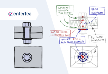
Bolts in FEA [5]: Complex Bolt Model
This is the 5th installment of the “bolt series”. In this article we will discuss: An Advanced Model…
30 September 2024Modeling bolts is without a doubt one of the FEA nightmares.
You will learn here what the failure modes for a bolted connection are. Understanding those will help you to decide which of those failure modes you wish to address in your FEA (and which you will calculate later by the code). This in turn will dictate haw will you have to model your joints in FEA!
As I mentioned before, I’m playing around with writing shorter posts – let me know if you like this.

In this series of articles I cover practical approach to bolt modeling. There are several parts you can read, and those are:
You model bolted connection in your FEA for a reason (somehow, I doubt you do this for pleasure!).
Here, we will wonder what you may want to obtain/analyze in your FEA outcomes.
Mind, that all the failure modes I will list here exist… but this doesn’t mean that you want to calculate each of them in FEA. Many of those can be calculated separately in post-processing.
The problems only arise, when those effects somehow interact with other things you have in your model (in which case you can’t really calculate them “separately” later). But this is a problem we will address in a later articles of the series.

This is most likely the most common thing you may want to check. In various geometries it may not be easy to assess what is the tensile force in the bolt. This is why you model bolts (and contact between plates of course) – this allows you to read the tensile force in the bolt directly from FEA.
Let’s get this straight: You DO NOT want to model the bolt accurately enough to calculate its tensile capacity directly in FEA. Limit yourself to reading the tensile load in the bolt, and checking its capacity by hand (simply using tabular set of bolt capacities).

Usually shear force distribution in bolts is easier to establish than tensile force distribution (unless you have torsion in the connection). This means that if you have a “clean shear”, you may not even model the bolts. But if you modeled the bolts due to other reasons, you may just as well check the shear force in them!
As in case of tensile failure, you don’t really want to model the bolt accurately enough to compute its capacity in FEA. It’s way more efficient to compare the shear force from FEA with the bolt shear capacity (calculated to the code, or from a table for a given bolt).
Slip Failure in pre-stressed connections
If you have a pre-stressed joint, when the friction is broken, and the plates “slip” one against the other, this is treated as failure (way before the bolts fail in shear, or some other failure happens).
But here, I treat “slip failure” as equal to shear failure, simply because you will check it against the same shear force you will read from FEA (although the values of capacity would be different for a pre-stressed and “normal” connections, in both cases it’s better to calculate them by the code).

This one is a mess. Usually bolts in bolted connections should not be significantly bent (code procedures don’t provide additional rules to consider that, they usually limit what you can do, to avoid the problem). Sure, under shear in “normal conditions” bolts are bent a little bit, but this is usually simply ignored.
Still in some cases significant local bending can appear. You may have a seal (in green above) that needs to be used in a connection in shear. Or maybe you have anchoring that uses a layer of weak grout before the anchor is embedded in concrete. Or even there is just “air” between plates you are connecting for some reason.
In those cases, bolts will be bent, and it will be a tricky thing. Of course this will combine with shear and tension (for bolt capacity), but the problem will be establishing the proper bending moment in the bolt. For this a classical 2D mesh “midsurface” model may not be sufficiently accurate I’m afraid.


Without a doubt, you may use an end-plate that is just too thin. In which case it may fail due to bending. Funny enough, this is way easier to show as a FEA outcome than a sketch (!).
For simple cases, this can be calculated using a rather complex code procedure (based on forces the connection has to transfer).
Still it’s more comfortable (and needed in anything other than the basics) to calculate this with FEA. This failure is based on stresses in the end plate, so analyzing it in FEA is actually doable, although care needs to be taken in how do you model bolts.

Bolts will touch the plate when transferring shear, and failure may not come from bolt shearing, but rather from plate failing due to contact pressure. This is one of the considerations for plate thickness (among other things).
This is relatively easy to calculate following the code, and a bit more tricky (although still doable) in FEA.

This is a whole selection of failure modes. The one I’m showing above would be a classical example. But I must confess, there is a murky line between bearing stress and block failure:
If you have a single bolt, too close to the plate edge, the plate will fail. Such a failure is somewhere “between” the bearing stress and block failure, but Eurocodes treat that as a bearing capacity (there are factors reducing the capacity related to small edge distance).
So to keep things consistent, let’s say that block failure is something like the above, where a chunk of steel is being reaped off by several bolts.
This is quite easy to calculate by the code, but you need to know the force in the connection (rather than forces in the bolts), it also gets trickier when you have more complex load patterns (i.e. including torsion). In FEA, this is doable, but it’s more on the tricky side, as far as the bolt modeling is considered.

This may be a bit more difficult to imagine at first.
Normally we associate tensile failure in bolted connection with bolt failing in tension and snapping. But what if you would have a very thin plate, and a big bolt?
It could actually happen that the nut of the bolt (along with a washer) would “punch” a bigger hole in that thin plate and “fly through” – that is punching shear!
While this looks pretty complex, calculating capacity of this type of failure by the code is actually pretty easy. Checking this failure in FEA won’t be difficult either. So it looks scary (and is scary if you use thin plates), but this is a solvable problem.

This is a tricky one. It’s still considered to be a connection failure (as opposed to plate capacity). However, you will not “calculate” this capacity. Instead, you will just follow the guidelines for bolt placement given in a code (for me, I always reference Eurocodes) and if you follow those guidelines, you are “safe” from this.
But let’s be honest, you may be in a situation where following the code guidelines is a luxury you can’t afford (connecting very thin plates for instance). In such cases, it’s very important to know that such a failure can happen, and be ready for it.
Calculating this by hand is posible, mostly by analogy to compressed elements, although figuring out the force and the width/length of plate you should treat as a compressed beam will require some estimation/guesswork.
It’s a bit more straightforward in FEA, but here, you need to be careful when consiedering which DoF are constrained by bolts, and why.
All in all, this is a tricky thing to design. Luckily, now you are aware of the problem, and that is always the first step to solving it!

This one is interesting – as according to Eurocodes this is NOT a connection capacity (but rather the capacity of the plate itself).
Logic here is simple: Sure, adding bolts helps to keep things together. But to fasten the bolts you need to make holes in the connected plates… making them locally weaker (i.e. in tension). This will not always play a role, but should not be ignored!
But you may have openings in the plate, not only because of the connections, so weakened cross-sections are considered as “plate thing” in Eurocode. I’m not sure if I’m a fan, treating this as a part of the connection design would make it easier I believe.
For a simple stress state (i.e. in tension) calculating this by the code is super simple. In FEA this will require a more advanced bolts modeling.
As you can see, there are PLENTY of things you can be worried about in a bolted connection, and all of those have to be addressed somehow.
Many capacities can be calculated “as per code” without the need to perform a really complex FEA analysis (if the forces in the bolts are known). Sadly, this only works if you can “isolate” a given thing, and that you are certain, that the stress a given failure model causes will not add to stress caused by something else. Because if they do add… then you need to model this in FEA.
In simple cases, those usually are isolated, and Eurocode doesn’t even provide interactions between various failure forms. But in plate/shell models this becomes way more complex, as end plates can be stiffeners at the same time, and stress patterns become complicated.
But this is a topic we will cover in one of the coming articles in the series!
Join my 2h FREE Live Event and learn all that you need to know to start using Nonlinear FEA as an Expert! I will talk about:



Share
Join the discussion