!function(f,b,e,v,n,t,s) {if(f.fbq)return;n=f.fbq=function(){n.callMethod? n.callMethod.apply(n,arguments):n.queue.push(arguments)}; if(!f._fbq)f._fbq=n;n.push=n;n.loaded=!0;n.version='2.0'; n.queue=[];t=b.createElement(e);t.async=!0; t.src=v;s=b.getElementsByTagName(e)[0]; s.parentNode.insertBefore(t,s)}(window, document,'script', 'https://connect.facebook.net/en_US/fbevents.js'); fbq('init', '366319058984917'); fbq('track', 'PageView');
8 minutes read
13 February 2017

Connection rigidity: 5 things you need to know!

8 minutes read

Most engineers use a popular approach: connection is either a hinge or a rigid one. This is usually not the case. Just as with many other engineering problems in certain cases we simplify the reality by assuming perfect conditions (i.e. hinge). It is crucial to understand when such assumptions are incorrect, as this may lead to severe problems!

1. Rigid connection is usually not as rigid as you think

As you know this is the poster boy of connection rigidity. Whenever I think about connection rigidity this is the first thing that pops to mind:

rigid connections aren’t all that rigid in reality

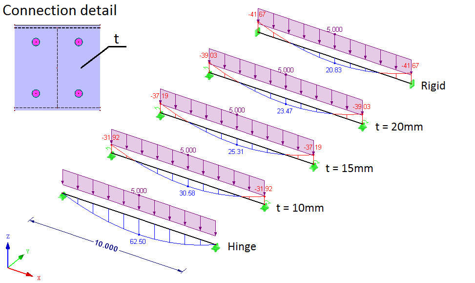
Unfortunately, the fact that you assumed in design that connection is rigid, has a small impact on real structural behavior. In reality, some rotation is possible in almost any geometric configuration. This means that the connection will rotate a bit, and thus is not “infinitely rigid”. This, in turn, will obviously have an impact on internal forces (especially bending moments) you receive in static design.

Such change is not 100% negative. Since you don’t transfer full bending moments some elements will be less strained (since they didn’t get the moment). Unfortunately, the moment does not disappear – it will be higher somewhere else.

As with everything in static design, you have to pay: if some element has better conditions, something else has worse conditions as a price. I.e. if you make a single-span beam with rigid connections at the ends, the deflection and moment in the beam span decreases (it is a clear benefit). On the other hand connections and elements that the beam is attached to now get bending and have to deal with it (this is the price).

Look at the schematic below, it clearly shows what I have in mind. The bending moment changes a lot with the different plate thicknesses in connection. Plate thickness t is simply changing the connection rigidity in this case.
If you are interested in this topic, read more here 🙂

2. Hinge is not always a hinge

This is the flip side of the same coin, but it is overlooked most of the time. We think that a hinge is a “worst-case scenario”, while in fact, it does not have to be the truth. Remember that:

whenever some element has it better in static design, some other element has it worse!

In this case, our hinge-wannabe connection will transfer some moment. The beam is happy – the more rigid connection the less moment is in the span. Unfortunately, the connection itself and the element the beam is attached to is not happy at all! They have to deal with the bending moment that was not foreseen in the design! This is clearly a problematic issue.

How to Reasonably do Nonlinear FEA Join me for free on October 20th

Join my 2h FREE Live Event and learn all that you need to know to start using Nonlinear FEA as an Expert! I will talk about:

  • How Nonlinear FEA really works
  • What to pay attention to during Analysis Setup
  • How to Analyze and Understand Outcomes
  • … and much more!
Sign up now!

Take a look at the “typical hinge connection” and an actual bending moment that is in the connection due to its rigidity:

Note that the fact the moment is shown in the diagram does not mean that the connection will carry it. It only means that the connection should carry it. But since we assumed in static design that it is a hinge, connection (and other elements that this beam is attached to) may be too weak. In such a case it will simply break.

If you are interested in this topic, read more here 🙂

3. Connection rigidity does make a difference

I strongly believe that we overlook connection rigidity, simply because we use past experiences. For decades engineers have designed steel structures without taking that into account and everything was fine… so we will as well.

Such an approach is actually pretty neat, as long as we will do it as those engineers before us. But now we try to optimize everything to the limit. Such an approach means, that now we cannot ignore problems that we ignored without problems a few years ago. To the point where current Eurocodes actually demand analysis of connection rigidity.

Whenever you optimize a structure up to those “magical” 100% bear in mind that there are effects that might influence the forces distribution in the model. In such cases, it is crucial to take connection rigidity into account!

There is another neat trick here:

if you connect HEB 300 to a paperclip it doesn’t matter if the connection is rigid or not.

Paperclip is so weak in comparison to the HEB, that regardless of the connection from the HEB standpoint it will be a hinge. Either connection itself will deform, or the paperclip will. This means that if you are making a connection to a susceptible structure check what if the difference is if you make a rigid or a hinge connection. If the difference is small and within an acceptable level, then connection rigidity won’t have a great impact.

Take a look at what happens if you take a beam from the first point and instead of fixing it, you connect it to a 7m column:
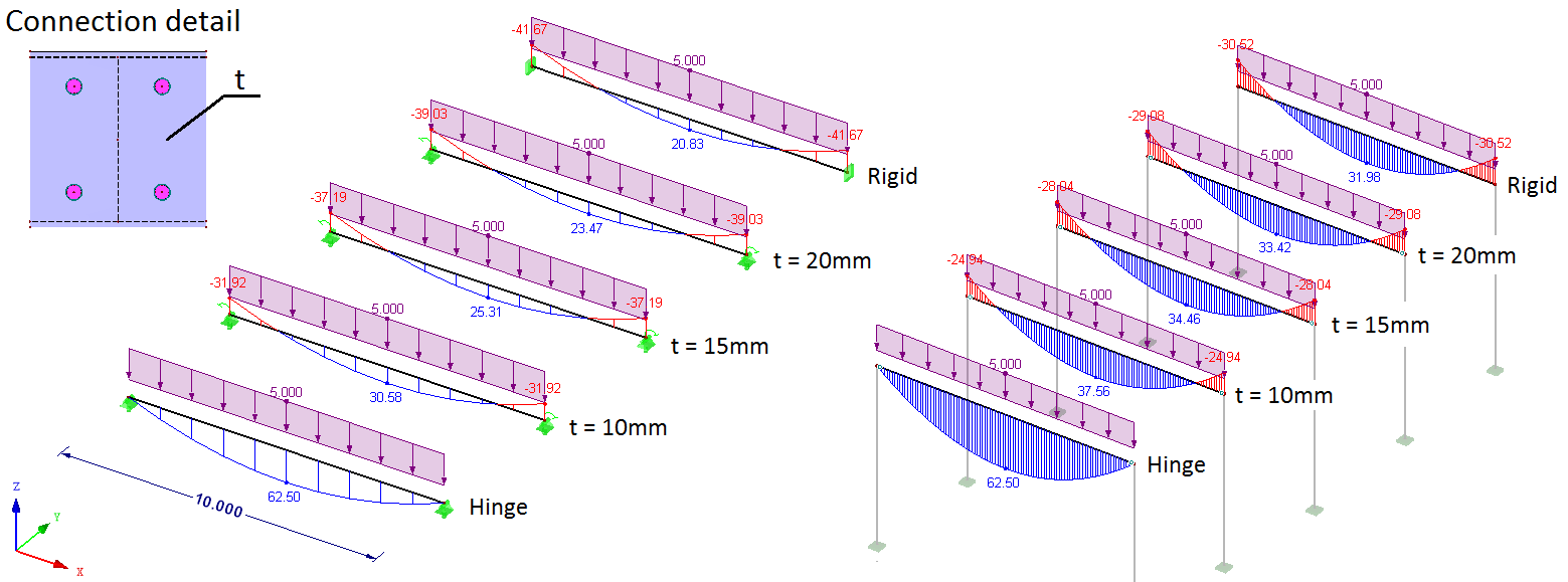
Note that in the “column case” on the right, the bending moment in the span is 50% higher than on the left schematic. It doesn’t matter that the connection itself is infinitely rigid – the columns deform and as such moment in span increases. Columns in this example aren’t exactly paperclips, but you get the idea 🙂

More on the significance of connection rigidity in this post.

4. Avoid slippage!

Connection rigidity topic is almost always about rigidity due to bending. All the above examples are about this part of the spectrum. However, you have to remember that each internal force can be transferred or not. As I wrote in this post:

If we are talking about rotational rigidity of the connection we expect the outcomes from the static design to be somewhere between those for a hinge and those for a rigid connection

If we are talking about translational rigidity of the connection the outcomes will be somewhere between those for a rigid connection and those with no connection at all!

This means that the impact of slippage is huge! To the point where it can lead to failure as I have described here.

Please remember that slippage of few millimeters can have a drastic impact on static design. As long as “everything” deforms uniformly, then only deformations will increase. Note that the increase is usually much higher than one would expect, as can be seen below (additional vertical deformation is 10 times higher than the slippage value):
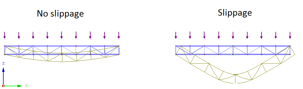
The most dangerous case is when some elements will “slip” while others will “take” the force. In other words, this means that parts of the structure won’t work as they should, simply because connections won’t transmit forces to those elements.

If you ever use shear bolted connections be sure to pre-tension them or at least check what happens if the slippage appears. This is one of the most dangerous phenomena in the connection rigidity field.

Learn more about slippage in bolted connections.

5. How to take connection rigidity into account

This part is easy. Now, almost all software solutions allow for connection and support rigidity definitions. Some may not allow for nonlinear parameters, but in most cases, linear estimation is enough. With the linear approach, you will only get problems with slippage which is nonlinear in nature.

The only problem is that taking that into account takes precious time. The introduction of the property is easy, but the estimation of the rigidity takes some time. Here you have 2 choices:

  • Follow a code of your choice. For example, EN 1993-1-8 gives quite specific guidelines on how to calculate connection rigidity. It is a lot of work for sure, but make yourself an excel sheet of VBA macro for it, and you will be just fine 🙂
  • Do a FEA model. Sounds scary, but if you know what you are doing it takes only a few minutes per connection. I’m a big fan of spreadsheets that do stuff, but I’m always concerned that my spreadsheet won’t be robust enough. FEA approach is better in this way, as you can simply calculate a rigidity of any connection you might have. You can read more about this approach here.
  • Let’s call this choice 2b – each problem is usually more complicated than it seems. Above you can see a simple linear model. As you are aware, at certain point elements of the connection will yield, and this will increase the rotation. So the above estimate is valid, as long as the connection remains elastic. When plasticity is involved, this gets a bit more complicated, as the stiffness depends on the actual moment value as shown below. If you wish to model it in a simplified way (i.e. linear) you have to know beforehand what moment values will be in the connection. This allows for correct estimation of secant stiffness.

Of course, you can also wonder, if the “classical” assumptions are correct in your case. I explain how to check if your connection is a hinge here.

If you have any questions feel free to leave them below in the comments section.

Author: Łukasz Skotny Ph.D.

I have over 10 years of practical FEA experience (I'm running my own Engineering Consultancy), and I've been an academic teacher for a decade. Here, I gladly share my engineering knowledge through courses, and on the blog!

Read more

Join the discussion

Comments (12)

Jeremy - 2020-10-08 19:26:45

Hi Lukasz

I have one for you. I am adding additional stories to an existing steel framed building. The existing lateral stability system (steel cross bracing) is not able to accommodate the additional sway induced by the additional stories.

The building does however have a lot of columns, which have steel composite beams connecting into them. The column beam connection is what you would classify as a simple bolted connection, with, angle cleats on either side of the beam web. Thus the current design assumes these as pinned and therefore do not contribute to the buildings stability. As far as I understand EN 1993-1-8 gives provisions for calculating connection rigidity for end plate connections.

I believe that these connections would contribute some degree of lateral resistance by way of generating a moment between the beam column. However, I don't think there is any code based way of justifying this, and I believe that it would need to be assessed using FEA.

I would be interested to hear your thoughts on this. I had thought that this strategy would be quite common place. However, from my research I can see that it is not often considered.

My best,

Jeremy

Reply
Łukasz Skotny Ph.D. - 2020-10-09 14:52:01

Hey Jeremy!

I've learned already never to assume that I understand how the geometry of the problem looks like based on a description of someone else :)

Do I understand correctly, that the connection is like this:

You have an I beam, that has 2 angles welded or bolted on both sides of the web (so there is no connection of flanges). And those L sections are in turn bolted to something else (like a horizontal beam or whatever...

If the above is ok, you only have the connection "on the web"... I wouldn't overvalue its rigidity - if the existing bracing is "too weak" then I don't think that even a bit of the rigidity that connection would give you would help you... I suspect that it won't.

But what you wrote is true, there is no way to calculate the rigidity of such connection according to eurocodes. You can, of course, do it in FEA - There is a post about how I would approach this on the blog :)

Hope this helps!
Ł

Reply
Ievgen - 2020-03-14 16:21:34

Many thanks for the post. Like to read it.

Reply
Łukasz Skotny Ph.D. - 2020-03-15 08:57:16

Thanks!

I'm really glad that you do :)

All the best!
Ł

Reply
Konrad - 2018-06-08 11:30:44

Lukasz,

just thought of something. Most of you are saying in the post is very clear enough to understand and keep the issue in mind. Anyway to use it in practice would be very appreciated if you could some time mention how to for instance model welds and especially bolts in FEM analysis software roughly enough to evaluate results and how to read connection rigidity from results. Unless it is already posted somewhere else and I missed that? Would be interesting to make some comparison between software like Dlubal or Robot and IDEA Statica that has this all already implemented, but in their specific FEM variation method.

Regards,
Konrad

Reply
Łukasz Skotny Ph.D. - 2018-06-08 14:06:01

Hey Konrad!

I haven't made such a comprehensive study. There is a lesson in my paid course about bolt modeling, but in a bit different aspect (in more detailed FEA).

Sadly, such a study would take a lot of time - and I'm already stretched thin. This means that even if I do one in future it will be most likely a "paid" content of some sort (like an example in the library or part of the course). And it is almost impossible to make comparisons like that, as I have licenses for RFEM and Femap only - and I can't really use soft for which I don't have a commercial license in this blog : (

Anyway, if you have the means to do such a comparison I would gladly help you and post it here : )

All the best
Ł

Reply
Konrad - 2018-06-08 09:15:51

Lukasz,

great post about the issue we discussed once. Well done!

Regards,
Konrad

Reply
Łukasz Skotny Ph.D. - 2018-06-08 10:56:43

Hey!

Thanks! I'm glad you enjoyed it :)

Ł

Reply
Alexandros Theodoridis - 2017-12-07 12:16:23

Hi Lukasz,

Rigid connectios are also the welded connections. (no bolts at all)
From the praxis point of view,my experience says that it is a bit more difficult to implement them in-situ because :
the very much accurate dimensions of the connecting members are required.
higher effort, time and possibly costs (especially in bigger heights of the structure) are needed.

Nevertheless, I think they give a slight more rigidity (K - stiffness) in comparison to the respective bolted connections, but that also depends on the particular geometry. And of course no slippage can occur.

So, what do you think?

Reply
Łukasz Skotny Ph.D. - 2017-12-07 20:08:41

Hey Alex!

I would say that welding is ok - but as you said there are many arguments against using it on site. Since I'm designing silos among others I'm not scared of welding on site (silos usually are!). However, in beam structures welding is not so common (still I once did a project for a roof where literally all connections were welded...).

When it comes to stiffness I would say that pre-stressed connection that is reasonably designed is as rigid as welding (or at least reasonably close to it). If pre-stress is not done, then welding should be more rigid - that is true.

Of course, "infinite" rigidity of the connection in actual design does also depend on the connection geometry etc.

All the best
Ł

Reply
Mewar - 2019-08-17 02:55:56

Welding does not have to be a rigid connection.
You can design it just to transfer shear.

Reply
Łukasz Skotny Ph.D. - 2019-08-17 20:21:01

This is a tricky part Mewar!

In general yes, I know what you mean. It's like the weld only to the web of the beam while the flanges remain unwelded yes?
In such a case, there is a certain rotation possible. It can be pretty high too... but it uses elastic (and then plastic) deformation of the weld in order to rotate. Depending on the connection geometry, and the required angle of the rotation this doesn't have to work, or can even have issues with low cycle fatigue (but I know you wouldn't make such a connection in a fatigue case, so it's a rather theoretical point).

It's like with everything in engineering. It works because most of the time the angle of rotation required is pretty small, and the deformations of the weld (elastic or plastic depending on the case) are still within a reasonable range. I can easily imagine where such a connection would fail due to excessive rotations as well of course. But the same can be said about many bolted connections as well!

Tricky stuff this connection rigidity!

Thanks for dropping in :)
Ł

Reply

Sign up for my FEA Newsletter!

Each Tuesday you will get awesome FEA Content directly to your email!

    Your personal data administrator is Enterfea Łukasz Skotny, Skrzydlata 1/7, 54-129 Wrocław/POLAND, Email. By subscribing to the newsletter that includes marketing messages you consent to your personal data processing in accordance with this privacy policy