

The chances and issues with 7 DoF (7th Degree of Freedom)
I assume that at this point, most structural engineers have heard about the mythic 7th Degree of Freedom (7…
27 May 2025Basics of Structural Rigidity are quite easy to explain. But the practical aspects are way more tricky.
I’ve recently had to solve an interesting rigidity problem in FEA. I figured it’s a good time to describe how to approach such issues. Especially since this is applicable both for structural steel design and FEA analysis!
But let’s start from the beginning!
I already wrote a few articles on structural rigidity. If you want a refresher, definitely check out my Gummy Bears Article.
To make intro short and sweet: imagine a wooden board supported on 2 stones and a rubber ball:

The wooden board is a beam, and you can easily see that it has 3 supports. But it’s also easy to realize, that the rubber ball is a “soft” support. It will deform a lot under load.
This means, that it will not take as much load as it would, if it would be made of stone. This is why normally speaking we use a “spring support” in such cases:
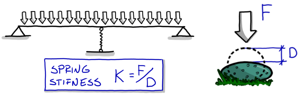
Imagine a case when the stiffness is high (the deformations under load are low). This would mean, that the middle support will act almost “normally”. In such case, we will get a solution close to a typical 2-span beam.
At the same time, you can imagine a case when the spring is very weak. It will not take almost any load (since deformations of the support will be huge). This means we will end up with a beam that acta as a single span beam. Sure, there is a middle support, but it doesn’t take almost any load.
In essence, this is the structural rigidity phenomenon.
How Structural Rigidity Works:
Things that deform less under a given load, will transfer more of that load.
In the above example we have 2 things that “deform” under the uniform load:
- Spring Support: If we treat the beam as 2-span beam we will get a reaction force on the middle support. The spring support will deform downward under this reaction force.
- Beam: If we would ignore the middle support, and simply treat the beam as a single span beam, the middle of the beam will deform downward under the load.
If the beam deforms a lot, and a support does not – the support will take most of the load, and we are close to 2-span beam!
But if the deformation of the support are huge, and the beam deforms only a little… it’s almost like the support was not there in the first place!
Of course, somewhere “in between” is, where the most interesting things happen, as we are neither here or there – we would get “in-between outcomes”.
This “competition” between deformations is structural rigidity in action.
Almost as if the various elements argue who can take the load, and the element that budged the least, takes the most of it!

Let’s see how the previous example translate to something practical. Firstly something a bit easier…
Imagine you’re designing a steel hall. The side wall, needs to have the windows in the fields with no bracings. You need to figure out a beam system to make this happen.
Considering the geometry, you end up with something like that:

This is a rather simple thing, so I guess we don’t have to discuss a lot of details here.
Imagine, that there is a rather big wind load on the wall. After initial calculations you see that the cross-sections you selected are too weak. Of course, you want to strengthen then, and this is where the fun begins!
It’s quite easy to create a static schematic for each beam (assuming both are continuous and connected to each other:

Note, that for the horizontal red beam, I marked the yellow columns as both spring support, and as loads. I did the same for columns representing the red beam this way.
There are two extreme scenarios here I want to point out first:
This leads to a funny game. Imagine the cross-sections of columns and a beam are similar (as far as structural rigidity is concerned). This means, that the beams “cooperate”, and they do things together. Neither is really a support for the other – they equally transfer the load, as they deform the same amount.
And now, as you want to make the capacity stronger, let’s say you increase the cross-section of the red beam:
In such cases, changing cross-sections run in circles. You end up in one of the extreme cases I started with!
Of course, the reasonable thing to do in such cases, is to increase both cross-sections at the same time. And while this would solve the issue, this leads to a bigger problem:
What would be the best way to set up such a structure? After all, equal rigidity of the columns and the beam may not be an optimal choice.
I want to show you a reasonable path forward, let’s discuss a more complex case!
Join my 2h FREE Live Event and learn all that you need to know to start using Nonlinear FEA as an Expert! I will talk about:
This time, we will have an insane amount of beams, all cooperating together (to varying degree). While this may sound like some theoretical puzzle, it’s a very common practical problem!
All you really need is a rectangular steel bin storing bulk solid. Something like this:

There are 2 effects in place, you need to be aware of:
As you can imagine, such a structure has to be modeled in FEA using 2D Plate Elements. But this means, that stiffener cross-section changes will be a freaking nightmare! Without a doubt there is a need to reasonably predict the cross-sections. But also to simply figure out how to solve the structure in the first place!
For the initial checks with cross-sections and their interactions due to rigidity, a reasonably well created beam model is enough. You just need to figure out a way to translate the loads into beam model. It’s also important to remember that the sheeting plate will cooperate with the stiffeners (so their cross-sections are bigger that what you weld onto the plate).
Focusing on the structural rigidity part of the problem in this article, we can divide the structure into 2 “camps”:


As you can imagine, there is a spectrum of solutions. Just like in the case of horizontal and vertical beams of the previous example… just way more complex!
It’s obvious, that making the vertical frames strong and rigid, we will allow the horizontal frames to be weaker. Of course this also works the other way around. We will need both types of elements (at least to some extent). But the proper way to distribute rigidity is not obvious at all!
There is an easy way to compare how “effective” each solution is. Just check how much they will deform under a “unit” load. At this initial step, I don’t really worry about the load value. After all the load to be transferred will be the same (regardless of the final solution). I just care, that the load is “big enough” so the deformations are clearly visible. Preferably higher than 0.12mm so it’s easier to read them!
This is how vertical frame can close the bending from support eccentricity.
You can see that the reaction force R is “translated” into a pair of forces “F”. This is due to support geometry (this is a huge simplification at this stage, but you get the idea).
You can see that the applied bending caused around 56mm of deformations to the outside. Sorry for not providing cross-sections and load values – it’s an industrial job, and I don’t feel comfortable sharing too many details.

This is how horizontal frame can close the bending from support eccentricity.
In this case, the horizontal frame will have to transfer either all the “F” forces to the inside (the top ring), or to the outside (the bottom ring). Below you can see the frame I calculated with the forces to the outside:

It’s very easy to see, that the deformation of the horizontal ring are MUCH higher than those of the vertical frame.
This means that the vertical frame is way more rigid (several times more!).
How to use this knowledge?
At this point it’s important to ask, what to do with this knowledge.
So far, we learned, that vertical frames are way more rigid. This is mostly since they are loaded with bending (and not “all the forces to the outside”). This means that their deformations are much lower.
This shows, that the structure “naturally” want’s to close bending from the support eccentricity on the vertical frames. Luckily we can have those!
We can of course “combat” this, by making the rings more stiff (and vertical columns much weaker). But I believe, that following what the structure actually “wants” to do naturally usually is the best approach.
This leads to a situation, where the “main frames” (thanks to the check, we know which ones should be treated as main!) are much bigger. Secondary elements are still needed of course. We need to transfer the horizontal pressure to the columns after all!. But they can be much smaller.
Of course, even here, there is an equilibrium. The smaller the secondary elements (assuming those are continuously welded of course) the bigger the columns have to be. Shortly: super small cross-sections aren’t that great, as the disproportion between sizes will make the connections tricky.

Based on the above, I was able to play around and figure out the best cross-section distribution for the model. Since changes here happen super quickly (with few clicks!) I was able to check an enormous amount of cases, and select the best setup of stiffeners.
With this, I have a very good insight into how the structure works, and what cross-sections to use. This is the best start for FEA modeling!
I’m sure we will have to tweak a few things when the accurate model will be made. But amount of iterations in FEA will decrease dramatically. Not to even mention the fact that quality of the solution will be great!
Thanks to this approach, I was able to check many various approaches, and compare potential solutions. That would simply be impossible in “only plate FEA” – it would take way too much time! This meant, that we’re starting FEA modeling already from a semi-optimal solution!
As you can see understanding such things can really skyrocket your design to the next level!
I like this approach mostly for that you can really optimize the structure before you even start serious FEA modeling. And you can consider not only the weight of the structure, but also ease of manufacturing and quality of details.
Especially the “quality of details” was important here, as this is loaded cyclically with a LOT of cycles. Fatigue considerations are critical… but it’s a story for another time!
I think that the best thing to remember here is that:
Structural rigidity is a static anti-hero!
It takes from the weak, and give to the strong!
Whatever you’re designing, you should know this. Often in the structures we design there are “competing” elements that can transfer a given load. The ones that deforms the least will take most of the load.
This has funny consequences:
When you have similarly rigid elements, be careful how you strengthen the structure. If you will start strengthening only one of those elements, it will take more load, and require further strengthening as a result! Of course, the other elements can be smaller then.
This is a vicious spiral, and it’s good to be aware, that sometimes it’s simply best to strengthen those weaker elements as well… just to escape this trap!
I hope you’ve enjoyed this one! Let me know what you think in the comments below!





Share
Join the discussion