


Structural Rigidity: Deep Dive
Basics of Structural Rigidity are quite easy to explain. But the practical aspects are way more tricky. I’ve…
26 January 2026Most engineers use a popular approach: connection is either a hinge or a rigid one. This is usually not the case. Just as with many other engineering problems in certain cases we simplify the reality by assuming perfect conditions (i.e. hinge). It is crucial to understand when such assumptions are incorrect, as this may lead to severe problems!
As you know this is the poster boy of connection rigidity. Whenever I think about connection rigidity this is the first thing that pops to mind:
rigid connections aren’t all that rigid in reality
Unfortunately, the fact that you assumed in design that connection is rigid, has a small impact on real structural behavior. In reality, some rotation is possible in almost any geometric configuration. This means that the connection will rotate a bit, and thus is not “infinitely rigid”. This, in turn, will obviously have an impact on internal forces (especially bending moments) you receive in static design.
Such change is not 100% negative. Since you don’t transfer full bending moments some elements will be less strained (since they didn’t get the moment). Unfortunately, the moment does not disappear – it will be higher somewhere else.
As with everything in static design, you have to pay: if some element has better conditions, something else has worse conditions as a price. I.e. if you make a single-span beam with rigid connections at the ends, the deflection and moment in the beam span decreases (it is a clear benefit). On the other hand connections and elements that the beam is attached to now get bending and have to deal with it (this is the price).
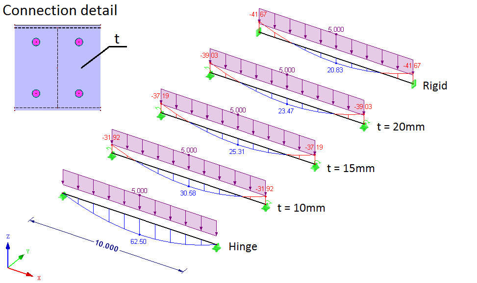
Look at the schematic below, it clearly shows what I have in mind. The bending moment changes a lot with the different plate thicknesses in connection. Plate thickness t is simply changing the connection rigidity in this case.
If you are interested in this topic, read more here 🙂
This is the flip side of the same coin, but it is overlooked most of the time. We think that a hinge is a “worst-case scenario”, while in fact, it does not have to be the truth. Remember that:
whenever some element has it better in static design, some other element has it worse!
In this case, our hinge-wannabe connection will transfer some moment. The beam is happy – the more rigid connection the less moment is in the span. Unfortunately, the connection itself and the element the beam is attached to is not happy at all! They have to deal with the bending moment that was not foreseen in the design! This is clearly a problematic issue.

Join my 2h FREE Live Event and learn all that you need to know to start using Nonlinear FEA as an Expert! I will talk about:
Take a look at the “typical hinge connection” and an actual bending moment that is in the connection due to its rigidity:

Note that the fact the moment is shown in the diagram does not mean that the connection will carry it. It only means that the connection should carry it. But since we assumed in static design that it is a hinge, connection (and other elements that this beam is attached to) may be too weak. In such a case it will simply break.
If you are interested in this topic, read more here 🙂
I strongly believe that we overlook connection rigidity, simply because we use past experiences. For decades engineers have designed steel structures without taking that into account and everything was fine… so we will as well.
Such an approach is actually pretty neat, as long as we will do it as those engineers before us. But now we try to optimize everything to the limit. Such an approach means, that now we cannot ignore problems that we ignored without problems a few years ago. To the point where current Eurocodes actually demand analysis of connection rigidity.
Whenever you optimize a structure up to those “magical” 100% bear in mind that there are effects that might influence the forces distribution in the model. In such cases, it is crucial to take connection rigidity into account!
There is another neat trick here:
if you connect HEB 300 to a paperclip it doesn’t matter if the connection is rigid or not.
Paperclip is so weak in comparison to the HEB, that regardless of the connection from the HEB standpoint it will be a hinge. Either connection itself will deform, or the paperclip will. This means that if you are making a connection to a susceptible structure check what if the difference is if you make a rigid or a hinge connection. If the difference is small and within an acceptable level, then connection rigidity won’t have a great impact.
Take a look at what happens if you take a beam from the first point and instead of fixing it, you connect it to a 7m column:
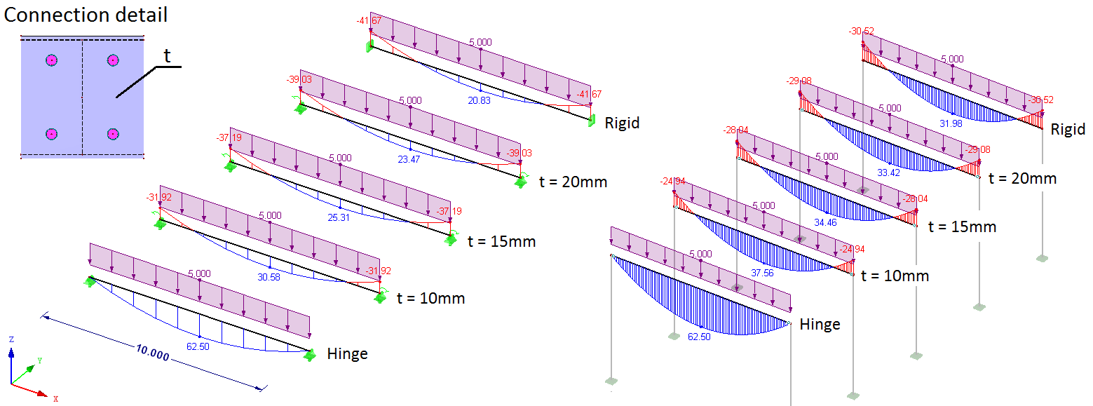
Note that in the “column case” on the right, the bending moment in the span is 50% higher than on the left schematic. It doesn’t matter that the connection itself is infinitely rigid – the columns deform and as such moment in span increases. Columns in this example aren’t exactly paperclips, but you get the idea 🙂
More on the significance of connection rigidity in this post.
Connection rigidity topic is almost always about rigidity due to bending. All the above examples are about this part of the spectrum. However, you have to remember that each internal force can be transferred or not. As I wrote in this post:
If we are talking about rotational rigidity of the connection we expect the outcomes from the static design to be somewhere between those for a hinge and those for a rigid connection
If we are talking about translational rigidity of the connection the outcomes will be somewhere between those for a rigid connection and those with no connection at all!
This means that the impact of slippage is huge! To the point where it can lead to failure as I have described here.
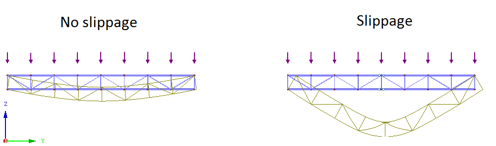
Please remember that slippage of few millimeters can have a drastic impact on static design. As long as “everything” deforms uniformly, then only deformations will increase. Note that the increase is usually much higher than one would expect, as can be seen below (additional vertical deformation is 10 times higher than the slippage value):
The most dangerous case is when some elements will “slip” while others will “take” the force. In other words, this means that parts of the structure won’t work as they should, simply because connections won’t transmit forces to those elements.
If you ever use shear bolted connections be sure to pre-tension them or at least check what happens if the slippage appears. This is one of the most dangerous phenomena in the connection rigidity field.
Learn more about slippage in bolted connections.
This part is easy. Now, almost all software solutions allow for connection and support rigidity definitions. Some may not allow for nonlinear parameters, but in most cases, linear estimation is enough. With the linear approach, you will only get problems with slippage which is nonlinear in nature.
The only problem is that taking that into account takes precious time. The introduction of the property is easy, but the estimation of the rigidity takes some time. Here you have 2 choices:


Of course, you can also wonder, if the “classical” assumptions are correct in your case. I explain how to check if your connection is a hinge here.
If you have any questions feel free to leave them below in the comments section.





Share
Join the discussion