
Structural Rigidity: Deep Dive
Basics of Structural Rigidity are quite easy to explain. But the practical aspects are way more tricky. I’ve…
26 January 2026This is a start of a design course I will publish on my blog. The aim is to show you the basics of design in FEA with some shell-specific issues. Several side-topics as mesh density or linear vs nonlinear buckling will also be discussed. I will make recordings of my preparations of models in Femap (with NX Nastran solver) used in the curse to make it easier to follow.

First, let’s look at the task. I picked a very simple shell, so the computing time will be short, but of course, the more complex designs I do at work are performed in exactly the same way (even though there is a lot more clicking involved). The shell I have chosen is shown in the figure below. The top load is 50 kN / m on the entire circumference (resulting in a total load of around 157kN).
Shell will be made from steel with Young Modulus E = 205GPa and Poisson ratio ν = 0.3. Since the model has 4 supports (each taking 10 degrees of shells circumference resulting in width s = 87mm) symmetry can be used to save computing time. I will model 90 degrees of the shell (with support in the middle) as shown below. Theoretically, a 45 deg model could be used (with a symmetry plane in the middle of the support), but since this is a place where the shell will fail in the future analysis I do not wish to use symmetry boundary conditions there.


Join my 2h FREE Live Event and learn all that you need to know to start using Nonlinear FEA as an Expert! I will talk about:
I will use 4 sided elements with 4 nodes each (commonly described as R4) with a FE edge size of 30mm. Shell will be supported on the top and bottom in the radial direction and pinned on the width of the support. On symmetry lines, boundary conditions are set for symmetry resulting in restraints in angular translation and rotations in R and Z directions (in a cylindrical coordinate system).
For now, I will not discuss assumptions regarding finite elements and boundary conditions. There will be a specific part in this course about finite element types and sizes, as well as the importance of boundary conditions later on.
For today I have planned the geometry preparation. If by chance you are using Femap, everything you need to do is shown in a 7min clip below. Whichever software you are using there are some general pointers to take into account:
When you apply the loads, boundary conditions, and mesh to the model it is time to check if everything went fine. To check my models I usually run a Linear Analysis just to see if everything worked as planned (you can see that check at the end of the video above). If you finished your model run such an analysis and you can compare the outcomes with the ones given below. If you have any problems feel free to leave a comment – I will try to help out
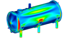
Here are the outcomes for the model described here and created according to the video. On the left: total translation (in meters) in the middle: radial translation (in meters) and on the right von Misses stress (in Pascals).

Have a nice day!



Share
Join the discussion