

Structural Rigidity: Deep Dive
Basics of Structural Rigidity are quite easy to explain. But the practical aspects are way more tricky. I’ve…
26 January 2026Today I will show you the nonlinear design process for coal dust hopper. This time tension will be the main issue (along with some bending), so the structure won’t be susceptible to stability failure. In such cases, the approach to design is slightly different, as I point out in this post.
I performed this analysis as the plant using those hoppers wished to evaluate if they can use them safely for the next few years. As in most hoppers, tension forces will be dominant, but since this one have “flat walls” bending will be also present. As material pressures will be outward the compressed part of vertical and horizontal stiffeners (due to bending) will be at the “inner” side, where those stiffeners are welded to the covering plates. This leads to a situation where stability failure due to lateral torsion buckling of said stiffeners is impossible (covering plates prohibit that). There were some challenges with loads as code EN 1991-4 does not specify exactly what to do in the analyzed case, but this is a topic for another post – today I wish to focus on the nonlinear analysis itself.
Instability failure won’t be an issue so I assumed that if the plastic capacity will be high enough there is no real advantage in searching for a lot of different imperfections sets that might induce stability failure. Of course, imperfections should be considered in the plastic design, but only as a factor in increasing stresses (which will lead to faster yielding). Also since the covering plates most likely work in membrane state (tension instead of bending) LBA analysis should not be trusted (as it cannot take that into account). Since the loading pattern was unclear several load sets were estimated, but for demonstration purposes, outcomes from only one are presented. The model has one symmetry plane, which I gladly used to reduce computing time.

As always I started with LBA analysis – I use it to verify if the model works as I assumed, everything is connected and loads are defined in the correct direction (I tend to use automatic load input, and the only thing that I do each time is deciding whether or not load should be negative). As you can see below LBA produced eigenvalues showing stability failures with a small load multiplier (only a little bit higher than 1.0). In most cases that would be a strong indicator that structure will have big issues with stability.
This time material nonlinear analysis was performed first. I omitted GNA which I usually do after LBA, as I knew that there is no real threat to stability. Of course, I will analyze stability anyway while performing GMNA analysis (if stability issues would be detected for whatever unforeseen reason I could always do GNA later). Since I switched geometric nonlinearity off in this analysis I knew that membrane state in covering plates won’t be taken into account so I predicted somewhat lower plastic capacity than the “real” one that will be obtained later. As it was hard to pinpoint the worst place in the structure, several stability paths were created using displacements of different points.


Join my 2h FREE Live Event and learn all that you need to know to start using Nonlinear FEA as an Expert! I will talk about:
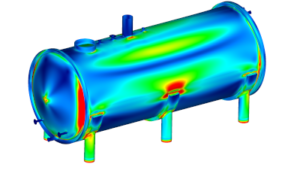
Note that maximal stress occurs in the middle sections of covering plates between stiffeners. This is the lack of membrane effect I mentioned before. Also, capacity can be seen below, and the first visual flattening of stability path appears around load multiplier r = 1.2.

Basically the final analysis for the project (even though additional GMNIA will be performed). In this analysis both mentioned previously effects can be seen: there will be no stability failure around load multiplier r = 1.0, and capacity if actually higher than r =1.2 shown in MNA due to membrane effects.

Note how different yield zone distribution is between GMNA and MNA analysis – this is the membrane effect in action. The same effect leads to a situation where the first flattening on the stability path in GMNA is visible after the load multiplier reaches 2.0 – this is a reason why the linear design of many systems is very conservative and shouldn’t be used in those cases! Also, there is no drop in stability paths (below) proving that there will be no failure contrary to what was predicted in LBA (which again is a linear algorithm).

At this stage, I could have ended the analysis. Yielding failure is mostly due to tension and “stabilized bending” (by this I mean there is bending, but there is no risk of lateral torsion buckling). I could search for imperfections for a long time, but in reality, there is no chance in such a structure to reduce the capacity with imperfections by 2.0-2.5 times! Instead, I want to show you a phenomenon that often occurs in such systems. If you would scale deformed shape from GMNA analysis you would obtain stress distribution as follows:

If you would compare yielding zones, you would notice that GMNIA produces less yielding than GMNA, since the structure was “prepared” to go into membrane state by initial imperfections. On the stability path it looks as follows:

You can see here that GMNIA analysis (dotted line) actually results in a smaller capacity (or at least higher deformations at the same load multiplier after the flattening occurs). If you look closely, you will find that in the region of r = 2.0 GMNIA produces actually smaller deformations than GMNA, since plotted deformations do not include initial imperfections.
This is an interesting occurrence, and it is worth remembering. If you ever encounter such a thing, I would advise considering imperfections in a negative direction, since you may be trying to buckle the structure that simply won’t buckle, and increasing stresses connected to reaching membrane state may be the worst-case scenario (in that case negative imperfections will force higher total deformations of the structure before reaching membrane equilibrium which in turn lead to higher stresses).
As you can see, there are a lot of variants of numerical analysis of any given structure. It is always worth it to think of the analysis and never have the same approach to different problems. For instance here analyzing GNA and searching for suitable imperfections for GNIA would be a gigantic waste of time (both working and computing time).
On a side note I’m on holiday with my family (just started today) so if I will be very lazy there might be nothing new here in 2 weeks… we will see 🙂
As always have a nice one!
Łukasz




Share
Join the discussion