!function(f,b,e,v,n,t,s) {if(f.fbq)return;n=f.fbq=function(){n.callMethod? n.callMethod.apply(n,arguments):n.queue.push(arguments)}; if(!f._fbq)f._fbq=n;n.push=n;n.loaded=!0;n.version='2.0'; n.queue=[];t=b.createElement(e);t.async=!0; t.src=v;s=b.getElementsByTagName(e)[0]; s.parentNode.insertBefore(t,s)}(window, document,'script', 'https://connect.facebook.net/en_US/fbevents.js'); fbq('init', '366319058984917'); fbq('track', 'PageView');
6 minutes read
28 February 2017

Design your silos with FEA – it pays!

6 minutes read

Designing steel silos with an analytical approach always yields very conservative results. Nonlinear Finite Element Method allows for great optimization of those structures (and other shell structures as well!). I will discuss this based on a silo I have recently designed.

Hero of today

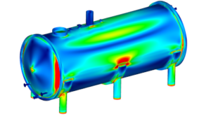
I will describe the advantages of the nonlinear numerical design of shells based on silos I have designed not so long ago. Below is a picture of the structure:

Analytical approach od silos design – a brief history

The history of designing silos with analytical equations is fascinating (at least for me :P). This is however not the main topic. Instead of going through all equations in EN 1993-4-1 or other similar codes, I will simply give you a short history. If this doesn’t interest you, skip this part 🙂

All I wish to say here is, that up to this day we are using the Timoshenko equation for critical buckling load of ideal uniformly supported/loaded shell. This is important, not only because the equation is almost 100 years old (the equation for the square area is somewhat older and still works), but also because this is the only closed analytical solution we have. In other words, if you want to design a shell that is supported on columns (like a silo) or not uniformly compressed from the top (a bit like a silo, I’m not picky) then… tough luck – there is no solution.

This leads to fabulous stories on how people tried to get around it. There were failures, some successes, and shocks. I.e. in 1992 Samuelson and Eggwertz published a book Shell Stability Handbook. They proved that stress in shells does not spread at a 45 deg angle but far steeper, meaning that concentrated stress… tends to remain concentrated with height. I can only imagine how bad a day in work I would have when I would learn that after designing several silos… I won’t even start describing the point when we realized how greatly shell capacity drops with imperfections.

Analytical approach to silos design – step by step

Generally, silos design is made in steps as shown below. If you are interested in post showing and describing all equations as well leave a mark in the comments.

  • Decide how accurately the shell must be made (there are strict rules for this step in EN 1993-1-6).
  • Calculate the imperfection reduction factor.
  • Think if “elephant foot buckling” (aka “plastic buckling”) is possible and if so update the imperfection reduction factor accordingly.
  • Use Timoshenko equation to calculate slenderness (regardless if you have uniformly supported/loaded shell or not). If your shell is supported on columns this is considered in imperfection reduction factor.
  • Calculate buckling reduction factor based on the slenderness and imperfection factor.
  • Stress in shell must be smaller than yield limit multiplied by buckling reduction factor.

Pretty reasonable right? There are a few issues with this approach, but all in all, this is a doable process.

How to Reasonably do Nonlinear FEA Join me for free on October 20th

Join my 2h FREE Live Event and learn all that you need to know to start using Nonlinear FEA as an Expert! I will talk about:

  • How Nonlinear FEA really works
  • What to pay attention to during Analysis Setup
  • How to Analyze and Understand Outcomes
  • … and much more!
Sign up now!

Note however that it still uses the Timoshenko equation and adapts it for the purposes of discretely supported shells. This is done with the imperfection reduction factor (its value is somewhat dependent on stress distribution along shell circumference). This is the place where a conservative approach appears, as such adaptation must be made on the safe side. This means the equations are “ready” for a worst-case, while your case is most likely not as bad 🙂

For our silos, the analytical capacity ratio due to vertical compression near column support is 117%. Sounds bad, right?

Finite Element Method approach to silos design

This is why I like Eurocodes so much (even though I am aware of all of the flaws). They allow for numerical design. Plain and simple. Code EN 1993-1-6 clearly describes what analysis should be performed, and when you can assume the capacity is sufficient. Also, those are no rules saying how much overstress (stress above yield limit) you may have here and there. A full-blown nonlinear analysis with imperfections is required.

This is really great 🙂 Even though nonlinear analysis isn’t the easiest approach, the benefits are incredible! Again I don’t want to go into details about how to do what – if you are interested take my free FEA course below this post!

The steps for FEA design are as follows:

  • Linear buckling. This is not an answer (far from it!) but it checks if the model works, where you can expect stability problems and let you roughly estimate where you are in terms of stability capacity.
  • Nonlinear buckling. This one is fun! You do not need a closed analytical solution for your case. You don’t need to adapt Timoshenko equation either. Solving nonlinear buckling gives you the answer you need.
  • Nonlinear buckling with imperfections. I mentioned this earlier, imperfections have a great impact on capacity. Of course, you never know which set will be the worse one, so you need to check at least several. Imperfections amplitudes are given in EN 1993-1-6.
  • Plastic collapse. The “second part” of the deal… no one claims that your shell will fail in an elastic manner. What about elephant foot buckling or plain plastic collapse. This is your answer.
  • Plastic collapse with nonlinear geometry. The first part of “interaction checking”. Now (after all the above steps) you know what is worse: elastic failure or plastic collapse. But surely they interact so you check how in here.
  • Plastic collapse with nonlinear geometry and imperfections… or nonlinear buckling with imperfections and plastic material. This is basically the same deal. Thing is that at this stage you know what will be worse and you will choose another set of imperfections based on that. Sometimes plastic collapse dominates (so you pick imperfections sets that further decrease capacity in this mode), sometimes elastic buckling failure dominates and imperfections change. After all, this is why you are doing all of the above: to understand how your particular case works, so you can act accordingly.

After all this work you look at the final stability path from GMNIA and you simply read the maximal load multiplier. A few factors later you have your designed capacity.

In the case of this silos capacity calculated numerically (according to EN 1993-1-6 and EN 1993-4-1) is 78%…

This means that the same capacity of the same silos under the same conditions is 50% higher when you calculate it with nonlinear finite element analysis. I think it is well worth the hassle, as material savings are significant!

In need of a good Nonlinear FEA design? Let us know!

Author: Łukasz Skotny Ph.D.

I have over 10 years of practical FEA experience (I'm running my own Engineering Consultancy), and I've been an academic teacher for a decade. Here, I gladly share my engineering knowledge through courses, and on the blog!

Read more

Join the discussion

Comments (18)

Tommy - 2021-10-11 16:25:29

Hi Lukasz, a very interesting article. I wanted to address this question: if one calculates some shell structure which have many stiffeners (e.g. rings or vertical) with GMNIA, does it mean only shell is checked against buckling or are already those stiffeners covered by GMNIA too? How to explain that, could you drop few words on that please? Thanks!

Reply
Łukasz Skotny Ph.D. - 2021-10-11 18:58:24

Hey Tommy!

Thank you for dropping in :)

This really depends on the situation. Without a doubt, they are covered with the GMNA... they are "there" after all. But sometimes stiffness can buckle on its own, and in such cases, they would need to have separate imperfection cases. It's doable, check I would do it if needed!, so you totally can do a GMNIA of the skell *with* stiffeners (otherwise that wouldn't be such a cool design method I must add!). In some cases it will just require some additional work, nothing else!

All the best!
Ł

Reply
Ievgen - 2020-06-26 11:25:24

Hi Łukasz.

I read your posts and comments to them with a grate pleasure. I do not design thin steel shell structures on daily basis, but most of general FEA rules, that you talk about, may be applicable in other special cases. Therefore, thank you very much for the blog!

Recently, I was "lucky" and got a structure of your expert field. It is an art-object of a traffic cone 6 m high and shall hang almost horizontally on facade of a building. Originally a client wanted to have it from stainless shells and hanged by cables in 2 points (start and end), hence I went to study EN 1993-1-6. Sections 8.7.2(23) to (26), about benchmarking of GMNIA model, were a big surprise for me. Have you dealt with structures in unique conditions that required such kind benchmarking? For example, the tank on a ship. It would be nice to read about such kind experience in general.

PS: about RFEM and GMNIA. Their stability module can check 1st non-linear buckling mode. I am not sure could RF-IMP convert it to an initial imperfection. But according to you comments above, I have understood that this is not enough to asses GMNIA model with it. Have I understood correct? Could you revise a little your answer.

Best regards

Reply
Łukasz Skotny Ph.D. - 2020-06-26 12:48:25

Hey Ievgen!

Benchmarking is needed indeed, and that is a good idea, to be honest. This is the only way a "code" can "check" if someone who is doing FEA knows what he/she is doing. After all, it's rather easy to get stupid outcomes.

So that being said, there are several benchmarks in the scientific literature. My favorite one is weld type A from prof. Rotter (big fan of his work!) there is even a post about it on the blog :)

As for RFEM and GMNIA, yea... there is no simple answer to this question. Luckily, you provided a clear example of what you are trying to do, so it's easier (whoever read this, please do not treat this as a "general, one fits all" answer).

To calculate shell buckling you basically need an Arc-Length algorithm implemented in your software. RFEM doesn't have that. While you can do imperfections the "analysis" possibilities are heavily limited. While you can try to analyze the model in GMNIA on the "stable part" of its work (when the capacity is ok) you cannot do that in the post-failure mode, since there is no arc-length. This, in essence, means that you cannot say what is the "capacity" you've got from your model (since you will never know when it will fail), but if you know what you are doing you could prove this way that while you don't know when it fails, you still can see that it is "strong enough". The problem is, that this means you cannot do any benchmarking, which is formally required in EN 1993-1-6.

Hope this helps a bit :)

All the best!
Ł

Reply
Ievgen - 2020-06-27 06:42:42

Yes, for sure, without doubts benchmarking is a must have for FEA. But, in case of unique structures, usually scientific papers are not available. Full size testing seems uneconomical cos it is not a mass production. Therefore only some FEA models of analogue full structure/parts is an only option comes to my mind. Next tricky question is 'How much similar the benchmarking model should be?' :) Strictly following EC '...The check cases should use basically similar imperfection assumptions and be similar in their buckling controlling parameters (such as relative shell slenderness, postbuckling behaviour, imperfection-sensitivity, geometric nonlinearity and material behaviour)'. It sounds to me, as an almost identical model.

PS: I have got your point about RFEM. It seems to me, design only in pre-buckling range may not be economical, but at least should be safe. As to design up to yeild. What do you think about that?

Best regards

Reply
Łukasz Skotny Ph.D. - 2020-06-30 06:18:23

Yea, this is a problem of benchmarking. I mean, I know what folks writing the text in the code had in mind... the world is a complicated place, and stuff doesn't always behave as you would like/predict. This is why you need to be extra sure if what you are doing makes sense!

But your points are... well... on point (yea... I'm that crafty with my words!). There isn't much one can do about it. Hoping to have the real-life testing in most cases is simply naive (but I admit I was involved in some of those as well!). Literature is scarce, but you can find some cool things (but this is a costly hobby as well if you don't have an institutional Elsevier subscription!).

My approach to this is, that I try to do "similar enough cases" for benchmarking. I'm a lucky guy, as I did some lab tests of shell buckling in my PhD, so I had where to start, and this covers the "vertical stability with stress concentrations" for me. Yielding is much easier to predict with hand calculations, so I feel a bit more secure there, ut you can always to some benchmarks there (I'm sure prof. Rotter wrote few articles with examples on this, but I can't recall titles sadly).

In other words, I try to classify problems into "buckets" (like vertical stability, circumferential stability, stability with yielding) and in each, I tried to do 1-2 benchmarks on as similar models to mine as possible. And now, when I approach a problem that is "vertical stability" I simply know that I can solve it, and I do this (so I don't search for benchmarks for every new project unless it is "super new" to me in some regard).

I hope this helps, even if a little bit!

All the best!
Ł

Reply
Dejan - 2020-04-22 14:43:01

Hi, Łukasz. Great article.

You already wrote aboute choosing software for particular use (we need general purpose software for solid and shell elements). But, I want to ask you, can this type of analaysis(GMNIA considering contact, offcourse) can be done with rfem, or in which percent can be done? I watched some video about analysis steel connections with rfem, and silo design, where they are considering contact and plastic behavior of plates, but I am sure that is not as good as it will be with nastran or ansys or abaqus. In most of cases companies doesn't has abaqus or nastran for designing civil engineering structure, because I am asking you that. :)

Reply
Łukasz Skotny Ph.D. - 2020-04-22 19:02:16

Hey Dejan!

This is a pretty tricky question, especially since it depends on how much YOU know about this whole mess!

In essence, you can't do a post-critical part of the stability chart of anything in RFEM. Sadly, they still haven't implemented arc-length, and perhaps this is not a priority for them.

This means, that you have to stick with the "stable" part of the stability path. And that is of course quite nice, but it may be hard to interpreter outcomes. Non-convergence can mean stability failure, or something completely different... and you will never know the "exact" capacity of the model not it's the failure mode. This is problematic since such shapes are often used as imperfection shapes (needed in GMNIA). So this is "murky" at best, as LBA shapes aren't great!

But if the RFEM folks would write on their page (I have no idea if they do that BTW) that RFEM is capable of doing GMNIA... there is truth to it - there is nonlinear material, you can do nonlinear geometry and you can invoke imperfections (there is a module for that called RF-IMP). The problem is, that not all imperfection shapes that may interest you will be available (perhaps scripts could be written, but you will never get the "post failure" shape...), and analysis of outcomes may be quite challenging.

Hope this helps!
Ł

Reply
Dejan - 2020-04-23 09:01:08

Your answer are very useful, thanks a lot. :)

Reply
Łukasz Skotny Ph.D. - 2020-04-23 11:17:52

I'm really glad that I could help you :)

All the best!
Ł

Reply
J. - 2019-07-31 15:11:37

Hi,

Thank again for the great blog! These are some good read for us engineers.

I've been struggling with Eurocodes for years, especially with shell buckling and seismic topics. There's always something not so clear....

Did I understand correctly, that with geometrically nonlinear analysis you can kind of simulate the buckling and post-buckling quite reliably, BUT that's is not enough according to Eurocode? Why is it? You need to go further and do for example the GMNIA?

If I'm right, there are practically 4 ways to do the check acc. to EC:

- LA, where you calculate the buckling resistance (which are only suitable for GLOBAL buckling) from equations and stresses from FEA or equations.

- MNA+LBA, where you calculate the buckling resistance using equations and FEA. Suitable for FEA models where there are holes nozzles etc.
OR, if MNA not available:
- LA+LBA, where you calculate the buckling resistance using equations and FEA. Suitable for FEA models where there are holes nozzles etc.

- GMNIA, mostly FEA, except some equations, and tables for imperfections..

I almost get headache when trying to read only the section 8.7.2. :D

But, what do you think of the division above?

Thanks!

Reply
Łukasz Skotny Ph.D. - 2019-08-01 06:19:38

Hey Juoni!

I'm really glad that you like my blog ;) I admit that Eurocodes, especially at the first read are nightmarish, but don't worry - it gets better when you get used to it :)

As to your question:

1. Shell stability with and calculations (approach 1) is pretty tough. There aren't many closed-form solutions, and most are based on Timoshenko shell. This means that a lot of conservative assumptions have to be made, and hand calculations inevitably lead to uneconomical design.

2. LBA/MNA thing would be cool... but somehow no one wants to spend time and create necessary parameters for any given problem. LBA/MNA gives you shell slenderness (assuming that you can reliably calculate MNA capacity which may be disputed, and I would rather make it GNA/MNA to include nonlinear geometrical effects but this is just a sidenote). The problem here is with the shell buckling itself. Even when you have the slenderness of the shell, you still need a couple od parameters to describe your "buckling curve" or at least check where you are on it. And it's more complicated (way more, like a Ph.D. topic) to create those parameters for any given problem, than to solve your shell with GMNIA (in face establishing those factors would require a LOT of GMNIA analysis of the same problem to obtain those parameters). In essence, if someone will do the job for a certain case... all other people can use LBA/MNA approach on this particular case... but I haven't seen a lot of solutions, mostly because you need to be able to do GMNIA analysis anyway, and if that is the case doing GMNIA is simply much quicker!

3. GMNIA - this is the "pure numerical design" approach. This way you can be much closer to the reality compared to the hand calculations in approach 1. so the design is much more economical. But you can't "only" do GMNA. You need the imperfections because shells are critically susceptible to them. A small set of imperfections (even tiny ones) can reduce the capacity by 60% as reported in many papers. Also, this can be proven in lab tests as well. Finally, the "perfect" shell from your GMNA analysis would have a much higher capacity in many cases than the "real" shell done according to the design. To avoid failures one have to take imperfections into account.

I really hope that this helps you - I must admit it took me a long time to understand all this!
If you have any more questions just let me know!
Ł

Reply
J. - 2019-08-01 11:12:15

Hi,

And thanks for the comprehensive reply!

My question was actually regarding Eurocode requirements (example citation below) for buckling analysis, i.e. which analysis procedures and steps are required/allowed, and if the 4 mentioned cases were the ones in your opinion also? But at least I see that you aren't rejecting my view on that. ;)

"(5) Geometrically nonlinear elastic analyses (GNA and GNIA) include consideration of the deformations of the structure, but none of the design methodologies of section 8 permit these to be used without a GMNIA analysis."

2. In my experience LA+LBA procedure is quite simple, straightforward and can be easily "productized" as method for frequent use in hectic project environment.

First you have to get the eigenvalues from FEA, then you pick few simple equations from 1993-1-6, including the one you place the eigenvalue into. Then you get the buckling resistance from the equations. Finally you compare the stress from FEA to resistance.

I haven't done MNA+LBA study so I don't know if it produces much economical results, but LA+LBA is at least all linear.

I didn't quite understand the rest of 2. starting from "The problem here is with the shell buckling itself....". Do you mean that it is not maybe possible to do MNA+LBA without GMNIA because the code won't give all the parameters? This I would understand some way.

And when I look at the GMNIA procedure from Eurocode (sample below), it doesn't look very simple to me :) Three different analysis cases for the start and some equations, and taking into account the imperfections aren't even mentioned yet!

"An LBA analysis should first be performed...."
"An MNA should next be performed on the perfect structure "
"These two resistance ratios should then be used to establish the overall relative slenderness λ − ov for the complete shell according to expression 8.25."
"A GMNA analysis should then be performed on the perfect structure "

-Jouni

Reply
Łukasz Skotny Ph.D. - 2019-08-01 12:25:59

Hey!

I'm not sure if I understand all of your doubts, but let's give this a swing :)

1. LA/LBA thing unless you are talking about pure hand calculations (so no LBA, only LA is required and some analytical work), then this is based on MNA/LBA approach (code chapter 8.6). This is not simple at all unless I seriously don't understand what you are doing. In the step you described as "then you pick few simple equations from 1993-1-6, including the one you place the eigenvalue into" you are making mistakes. In EN 1993-1-6 there are 3 procedures: to calculate uniformly supported and uniformly compressed shell (there are two for vertical and circumferential compression) and the third one is for shell in shear. The procedure uses several parameters like: lambda, beta, and eta. You don't have those for your case! It is specifically stated in EN 1993-1-6 chapter 8.6.2 (9) that you need to be "super careful" when establishing those parameters for your case, and you cannot simply take the ones from the code! This is why LBA/MNA approach doesn't work all too well. Simply establishing those parameters for your case is more work than doing the GMNIA itself!

2. GMNIA usually takes more than 2-3 analysis. Usually more like 5-8 but this is strongly case-dependent. Sure it's a lot, but at least you get decent outcomes with it that allow for reasonable design. This is my design method of choice, since in my opinion the LBA/MNA approach is simply impossible to do, and hand calculations are way too conservative (think Iljuszyn criterion - first point yields=failure!!)

Hope this helps a bit :)
Ł

Reply
J. - 2019-08-01 15:04:33

Hi,

A bit difficult in this blog format.. But if you carefully read through the section 8.6. you can find out that you don't need to do MNA (8.6.2.4). You get the slenderness (with the slenderness equation and eigenvalue(LBA)+stress(LA) at certain point in shell from FEA) and other parameters from section 8 and Annex D as it is stated. So 2 rounds of FEA, to get the membrane stress (LA) at point where the eigenvalue (LBA) exists. And of course many rounds more if need to optimize..

It is also noted that with certain shell types you have to be extra careful, but not what I'm mostly talking about, cylindrical shells, like simple ground-supported tanks in seismic load for example.. I tried a quick search to find some good example with a link and found this, which might be similar case https://resources.scia.net/en/garage/shellbucklingcheck.htm

Hopefully it is more clear now, but I'm happy to help if needed!

-J

Reply
Łukasz Skotny Ph.D. - 2019-08-02 10:45:35

Hey!

Yes... but the provision of chapter 8.6.2.4 is extremely conservative! It basically tells you - the first point that yields mean shell failure! This is often over 5x less than usual plastic capacity (depending on plate thicknesses and stiffening of course) - not the best deal for sure! This is precisely why linear analysis isn't cool in this case and the nonlinear approach gives simply so much better outcomes. Still, I won't argue this part is at least "doable" in a "technical" sense, regardless if it is economically justified or not.

The problem starts with what you wrote later... that is that you take parameters from section 8 and Annex D. I'm talking about equation 8.15 that requires you to know certain parameters listed under the equation. Those are: alfa, beta, eta and lambda_zero. Remark 1 tells you that you can take those from annex D but it also tells you that for cases not described in annex D you should search in the national annex... and if they are not there, well you are on your own.

So let's see what annex D can give us:

D1 - unstiffened shells. This is pretty gruesome. Any vertical, circumferential stiffener on your shell and you cannot take provisions of anything given in chapters starting from D.1...

D 1.2.1 (1) - vertical compression, only with BC1 or BC2 boundary conditions at both ends. In essence "uniform vertical compression". Good luck in finding a shell like that. Something is always "amiss" and I'm not even talking about hatches (even those would count in certain occasions I think) but columns, lack of rings, some weird loads like non-uniform roof loads fro equipment, live loads or ladders. All of that stuff. In those cases, you CANNOT take the parameters given in D.1.2. And this is not a trivial thing! It can be easily demonstrated that the shell with local buckling (over the column) has drastically lower capacity than the shell uniformly supported (as assumed in D 1.2). I haven't watched the video you linked to (it's an hour-long!) but I skimmed it and I saw they calculated a silo on columns. A perfect example of a shell that cannot be used here!

D.1.3 circumferential compression. They let you off the hook from boundary conditions, but they request that you use uniform load along circumference (and of course a constant thickness across the entire height of each shell segment!). This can be doable at last, even though the constant thickness is a mood killer if you ask me!

D.1.4 Shear. Again BC1 and BC2 boundary conditions. This could happen though, I'm pretty relaxed here, mostly because you would have to make a rather specific shell to have problems with stability due to shear. Been there several times, but usually by the looks, one knew that something is "off". So I don't really worry about this one :)

D.1.5 combination od D.1.2 and D.1.3 acting together. Good to have that around but it doesn't change the assumptions

D.1.6 D.1.2 D.1.3 and d.1.4 acting together. the procedure is wicked! But it's there, and still, doesn't change the assumptions, just allow you to cry in blood when you try to do that ;)

Then you have D.2 - still only unstiffened shells, but you can change thickness along the length - cool thing, even though I'm not the fan of how vertical compression is being treated. Again, a single difference in your shell and you can't use those!

D.3 and D.4 deal with some special kinds of other unstiffened shells... but it is not too important I think, unless you are into cones.

And that is that...

WAIT!

What about any stiffeners in my shell. You now like the ones you should give over columns, near openings and stuff. Well tough luck! There are no rules. This means that if you have a non-uniformly supported shell in vertical compression, or you used a single stiffener you are out of luck. There are no parameters in annex D you could use. There is a procedure of calculating those for any given case... but it is far quicker to simply do the proper GMNIA analysis instead (procedure for the parameters assume you will do a LOT of different GMNIA procedures and draw conclusions from them to get the parameters).

Yea... as I wrote before I'm afraid this is not as simple. Sure, if you have a uniformly supported tank on the ground than things might be doable if you "stretch" the rules here and there. But for anything else... that won't work. And this is not a trivial thing. Those parameters impact outcomes seriously and you shouldn't just "guess them". Heck, it's even directly written in the code that you should "pay a special attention" while calculating them!

I hope that now this is a bit more clear for you. Let me know if you have any more questions.

And in the end, I'm so sorry that this is this way... I draw no pleasure in writing this, nor am I happy because I have the time and knowledge to do GMNIA analysis so I have the advantage. It's not me "defending my turf" because it took me a decade to learn this and now I defend my effort by scaring you into learning or something. I remember full well how pissed I was at this when I was starting learning this all. I literally thought that there was a "conspiracy" of people that could do GMNIA that was aimed at all others to "secure the market" for those few who could do the analysis (seriously, it was really my theory!). Now I know that this is simply too complicated to put in a few simple equations... and even if those would exist, equations are done by scientists that now commonly know how to do GMINA, and instead of simplifying equations they prefer to discuss different imperfections in analysis etc. to further the craft they use in design, rather than do equations they themselves won't use anyway. That is something I can easily understand myself... as I would most likely do the same things if I were still at the Uni.

So to end with something slightly less pessimistic. There is a range of everything. Sure, one small stiffener technically disallows you to use all of Annex D parameters, but we know that it won't change that much right. So even as this is "against the code" using those may not be a terrible idea (even though the very conservative estimate based on LA analysis would be a killer, as that stiffener would concentrate stress!). But taking parameters for vertical compression of the uniformly supported shell while it stands on columns... that is a really bad idea in my opinion. So while such an approach can be used "sometimes", usually in the design I do it wouldn't be wise, to the point that I always do GMINA analysis when I do shell design. Sure, it takes more time and requires knowledge, but at least I'm sure about the outcome, and also I can optimize the structures like crazy still being within the code requirements. I can assure you that with LA/LBA approach I could easily prove that most shells should surely fail (even if they don't). And the problem is not that the method is over-conservative. The problem is that when you know it, you may want to design something that does not fulfill code criteria... it will most likely work BTW, but it will be your and only your fault if it doesn't. And this is a scary thing! You can read about it more here: https://enterfea.com/design-rules-vs-physics/

Well, I hope that this is helpful. And I really do wish you all the best in your learning! If you will have more questions never hesitate to write, I will be more than happy to help :)

Reply
Vasilis Rekatsinas - 2018-05-05 13:27:49

Dear Łukasz Skotny, very intresting article. Have you ever designed steel silos for buckling in high seismicity areas? In your experience seismic or static situation is more critical? From my experience in concrete silos, loading on silo bin is a bit tricky especially in seismic situation. How critical is for buckling analysis the correct modelling of loads from the filling material? Correct means....according codes and in particular Eurocodes.

Reply
Łukasz Skotny Ph.D. - 2018-05-05 18:52:27

Hey Vasilis :)

I've never designed seismic silos so far - I didn't get a chance, but I hope it will change someday (there are no real seismic problems around here). I did design silos mounted on ships, so apart from the "code difference" accelerations from waves is an acceleration after all :)

I would say that seismic stability would be a fun analysis. It does not necessarily be a deciding case, but this, of course, depends on the seismic zone and all. It would mostly increase the load on one side of the silo wall at a time - unsymmetric loads are never a good news for sure!

All the best
Ł

Reply

Sign up for my FEA Newsletter!

Each Tuesday you will get awesome FEA Content directly to your email!

    Your personal data administrator is Enterfea Łukasz Skotny, Skrzydlata 1/7, 54-129 Wrocław/POLAND, Email. By subscribing to the newsletter that includes marketing messages you consent to your personal data processing in accordance with this privacy policy