

Pressure Vessel Failure: Case-Study
We were recently hired to investigate the cause of pressure vessel failure. In my line of work, I can…
18 February 2026Have you ever performed an analysis that did not converge, or that ended with the result you did not expect? Many of such problems are resolved with correct solver settings, and today I will discuss how to set an arc-length geometrically nonlinear analysis of a shell. This means we will do a nonlinear buckling problem from scratch!
Before we start a checklist of things worth knowing before starting this tutorial:
Since I have already decided that I want to use the arc-length method to trace the stability path now it is time to set things up. Arc-length methods in most solvers require few parameters in order to work properly.

Join my 2h FREE Live Event and learn all that you need to know to start using Nonlinear FEA as an Expert! I will talk about:
In NX Nastran parameters described above have the following names and meanings:
The above parameters are not all of course but are the most important. Also, there are certain things to those parameters I did not mention (like the fact that some of them may have negative values which will be interpreted somehow by the solver). For now, I assume this is enough to perform simple nonlinear analysis. In Femap, those parameters are set in two windows of the “nonlinear analysis options” tab. Those windows are shown below:
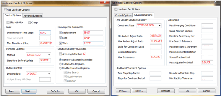
Apart from the parameters I described above, I marked a few others. KMETHOD and KSTEP are responsible for stiffness matrix updates during calculation run, and TYPE defines different arc-length strategies (modified Riks is the most popular, but I also use Crisfield). MAXR is a parameter that steers the process of increasing/decreasing load increments – you can limit how big an increase/decrease is acceptable. With [2] I have marked a box that must be checked – otherwise Femap won’t generate the NLPCI keyword and all parameters defined in “Advanced Options” will be ignored (resulting in non Arc-length analysis).
There are of course other parameters but for now, let’s leave them at default values in order to avoid long theoretical discussions. For the same reason I am avoiding going into the NX Nastran input file (the instructions generated in Femap for NX Nastran solver), but with a more complex design, it is actually worth learning the NX Nastran code to some extent (to be honest this is how I learn things – I learn NX Nastran code and when I know what I want I simply search which field in Femap are responsible for parameters I wish to set).
Below parameter values, I used in geometrically nonlinear analysis (note that leaving something “blanc” will use default NX Nastran value, even though most things are already filled in with default values in Femap just in case!). Important thing: the default value of MXINC is only 20 so you almost always want to fill that field since 20 is not enough in most cases).

The outcome of this analysis was already shown previously. I used the vertical displacement of the node on the shell top on a horizontal axis, and a force multiplier multiplied by the load I imputed (50kN/m), meaning that when the “set value” is 0.500 this means the current load is 0.5 x 50kN/m = 25kN/m. Obtained results are below.
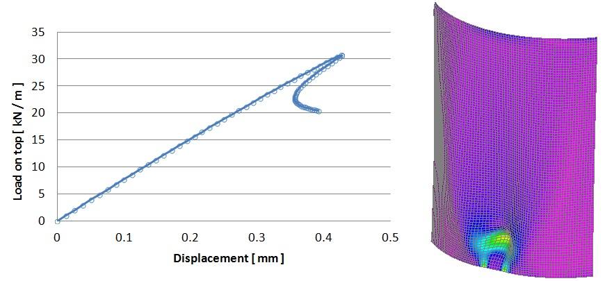
As written here results differ from those obtained in LBA.
And finally a video tutorial – I already ordered new gear to play with so there is a chance that the next tutorial will be recorded with my commentary that won’t sound like broken radio 🙂
Have a good one!
Łukasz



Share
Join the discussion